Flow regulation mechanism for turbocharger compressor
- Summary
- Abstract
- Description
- Claims
- Application Information
AI Technical Summary
Problems solved by technology
Method used
Image

Examples
Embodiment Construction
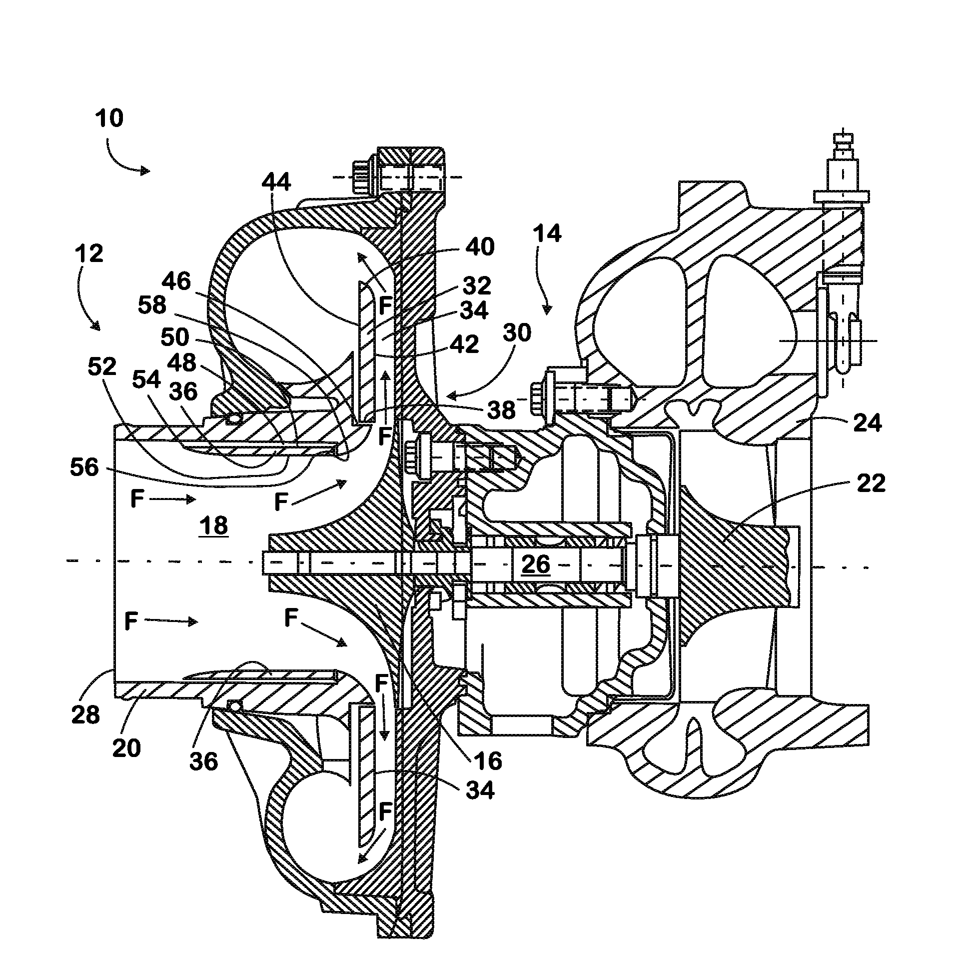
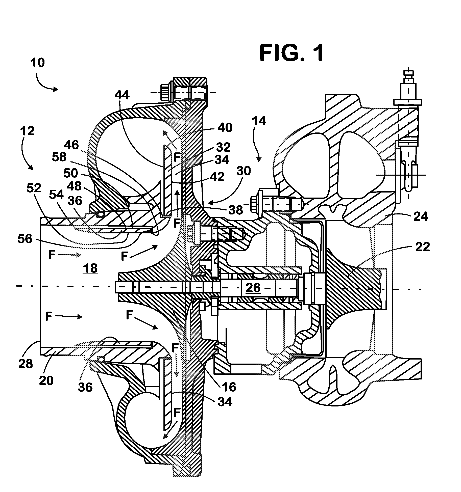
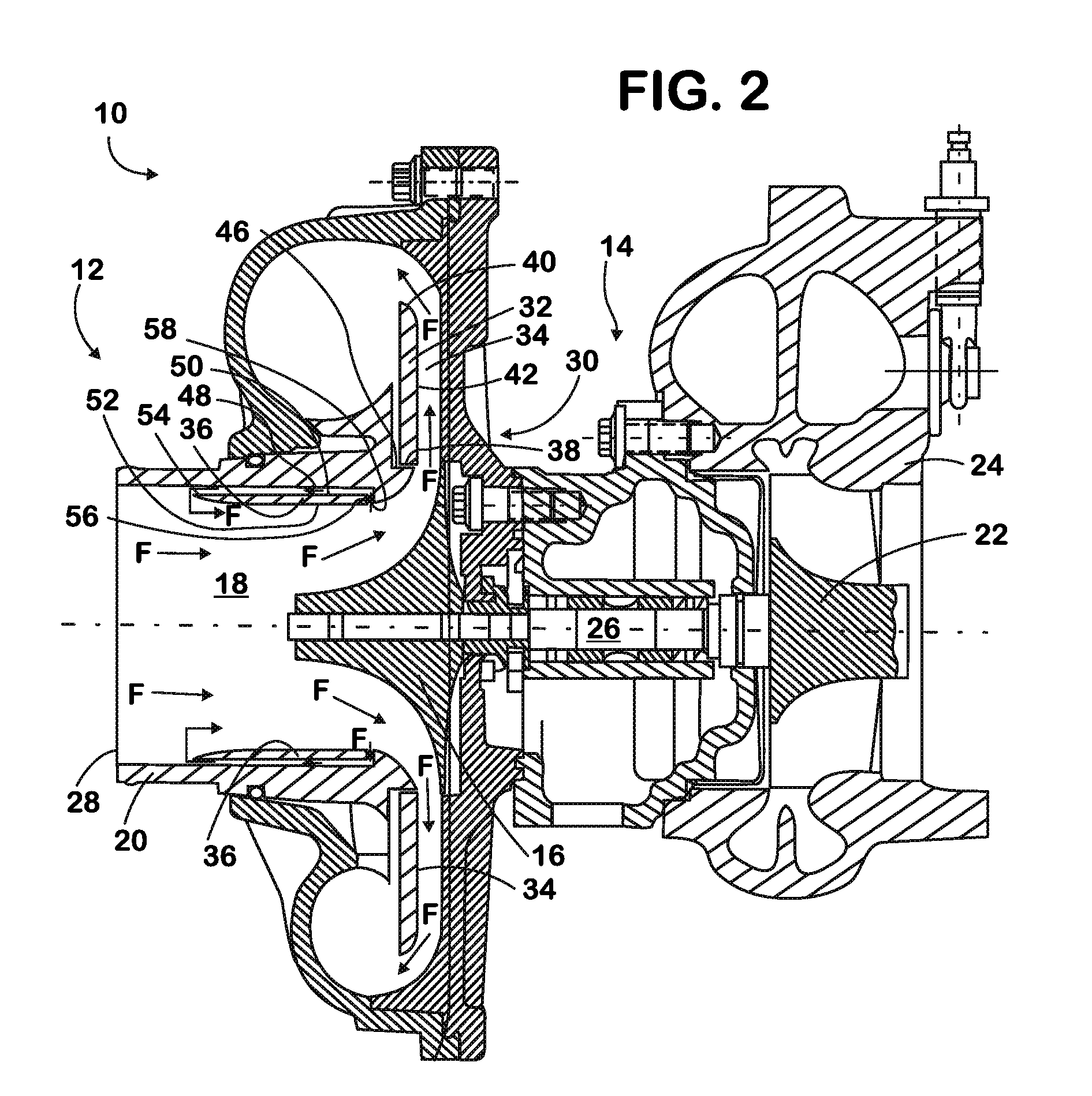
[0011]Referring to FIGS. 1 and 2, a turbocharger is indicated generally at 10 and includes a compressor 12 and a turbine 14 attached to the compressor. The compressor 12 includes a centrifugal impellor 16 positioned to spin inside a compressor chamber 18 formed by a compressor housing 20. The turbine 14 has a turbine wheel 22 positioned to spin inside of a turbine housing 24. Typically, the turbine wheel 22 is connected to the centrifugal impellor 16 through a common shaft 26, and the turbocharger 10 is mounted near the exhaust manifold of the engine (not shown).
[0012]Intake fluid “F”, generally air and possibly air containing exhaust gas recirculation (EGR), is introduced at a compressor inlet 28. The fluid “F” flows from the inlet 28 into the compressor chamber 18 where the spinning centrifugal impellor 16 pressurizes the intake fluid flowing through the compressor housing 20 to cylinders in an engine (not shown).
[0013]Generally, a turbocharger 10 spins faster when the engine spee...
PUM
 Abstract
Description
Claims
Application Information
 - R&D Engineer
- R&D Manager
- IP Professional
- Industry Leading Data Capabilities
- Powerful AI technology
- Patent DNA Extraction
Browse by: Latest US Patents, China's latest patents, Technical Efficacy Thesaurus, Application Domain, Technology Topic.
© 2024 PatSnap. All rights reserved.Legal|Privacy policy|Modern Slavery Act Transparency Statement|Sitemap