

Glass film laminate, glass roll of the laminate, method of protecting end face of glass film, and method of producing glass roll
- Summary
- Abstract
- Description
- Claims
- Application Information
AI Technical Summary
Benefits of technology
Problems solved by technology
Method used
Image

Examples
Embodiment Construction
[0037]Hereinafter, preferred embodiments of a glass film laminate and a glass roll of the glass film laminate according to the present invention are described with reference to the drawings.
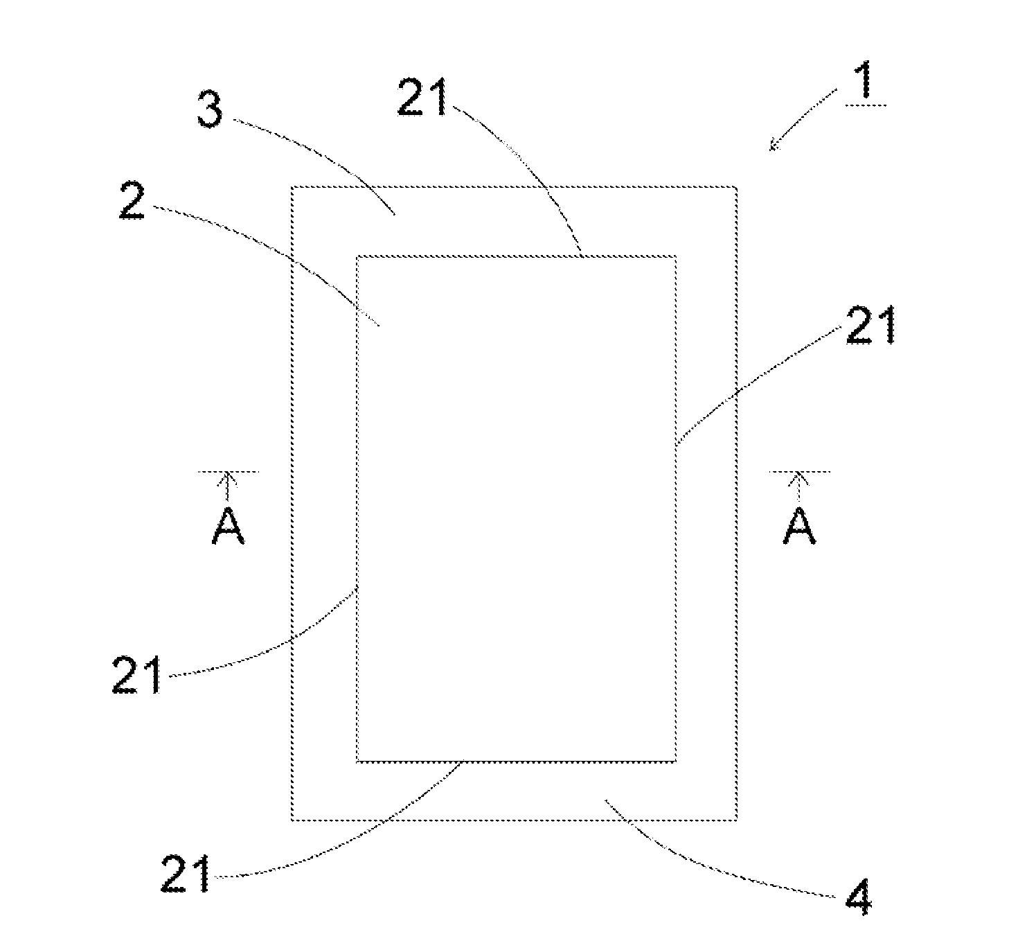
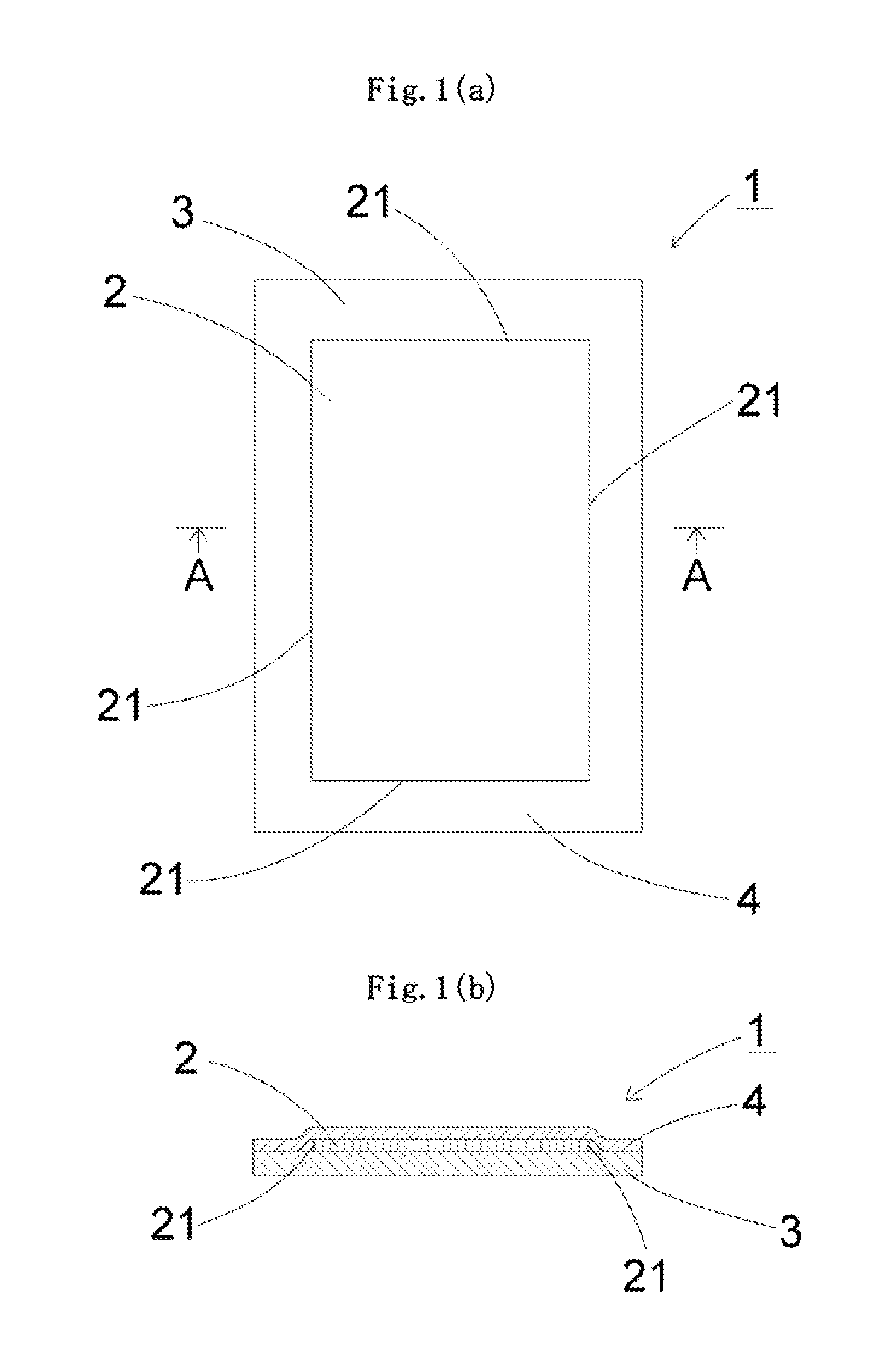
[0038]As illustrated in each of FIG. 1, a glass film laminate (1) according to the present invention has a glass film (2), a support glass (3), and a protective film (4).
[0039]A silicate glass, preferably a silica glass or a borosilicate glass, or most preferably a no-alkali borosilicate glass is used in the glass film (2). When the glass film (2) contains an alkali component, the substitution of a cation occurs on its surface. As a result, the so-called soda blasting phenomenon occurs, and hence the film becomes structurally rough. In this case, when the glass film (2) is used while being curved, the film may break from a portion that has become rough owing to age deterioration. It should be noted that the term “no-alkali borosilicate glass” as used herein refers to a glass substantially free of...
PUM
| Property | Measurement | Unit |
|---|---|---|
| Thickness | aaaaa | aaaaa |
| Thickness | aaaaa | aaaaa |
| Energy | aaaaa | aaaaa |
Abstract
Description
Claims
Application Information