Automatic gain control apparatus and method

Active Publication Date: 2010-10-14
HIMAX TECH LTD
View PDF13 Cites 5 Cited by
  • Summary
  • Abstract
  • Description
  • Claims
  • Application Information

AI Technical Summary

Benefits of technology

[0006]One of the objectives of the present invention is to provide a low cost gain control circuit and the related gain control method.

Problems solved by technology

Since the configuration of the radio signal receiving module 100 is a feedback control configuration, the stability issue can be a critical problem of the radio signal receiving module 100.

Method used


Image

  • Automatic gain control apparatus and method
  • Automatic gain control apparatus and method
  • Automatic gain control apparatus and method

Examples


Embodiment Construction

[0016]Certain terms are used throughout the description and following claims to refer to particular components. As one skilled in the art will appreciate, electronic equipment manufacturers may refer to a component by different names. This document does not intend to distinguish between components that differ in name but not function. In the following description and in the claims, the terms “include” and “comprise” are used in an open-ended fashion, and thus should be interpreted to mean “include, but not limited to . . . ”. Also, the term “couple” is intended to mean either an indirect or direct electrical connection. Accordingly, if one device is coupled to another device, that connection may be through a direct electrical connection, or through an indirect electrical connection via other devices and connections.

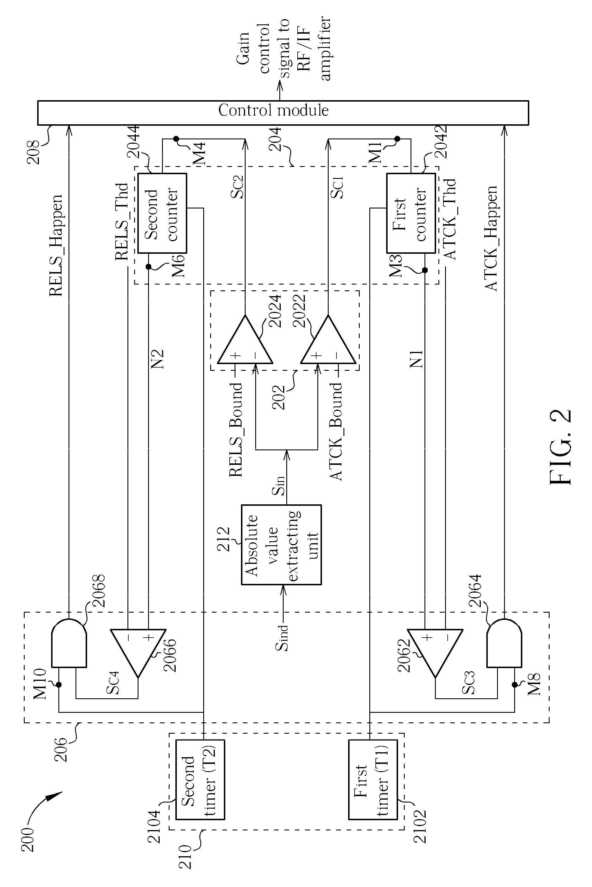
[0017]Please refer to FIG. 2. FIG. 2 is a diagram illustrating an AGC apparatus 200 according to an embodiment of the present invention. In this embodiment, a first opera...


PUM


Abstract

An automatic gain control apparatus includes a first comparing module, a counting module, a second comparing module, and a control module. The first comparing module compares an input signal with a first threshold level and a second threshold level to generate a first compared output signal and a second compared output signal respectively. The counting module performs counting operations upon the first compared output signal and the second compared output signal to generate a first counting number and a second counting number respectively. The second comparing module compares the first counting number with a first threshold number to generate a first detection signal and compares the second counting number with a second threshold number to generate a second detection signal. The control module controls the gain of a radio frequency amplifier or an intermediate frequency amplifier according to the first detection signal and the second detection signal.

Description

BACKGROUND OF THE INVENTION [0001]1. Field of the Invention[0002]The present invention relates to an automatic gain control apparatus and the related gain control method, and more particularly to a low cost automatic gain control apparatus.[0003]2. Description of the Prior Art[0004]Please refer to FIG. 1. FIG. 1 is a diagram illustrating a conventional radio signal receiving module 100, such as a digital television receiver. The radio signal receiving module 100 comprises an antenna 102, a radio frequency amplifier 104, a mixer 106, a SAW (Surface Acoustic Wave) filter 108, an intermediate frequency amplifier 110, an ADC (Analog-to-digital converter) 112, and a AGC (Automatic gain control) apparatus 114. The radio signal receiving module 100 is utilized to receive a radio signal Sr and output a corresponding digital signal Sd to a demodulator 116. The AGC apparatus 114 is utilized for detecting a power of the digital signal Sd and for adjusting a gain of the radio frequency amplifie...

Claims


Application Information

Patent Timeline
IPC IPC(8): H04B1/06
CPCH03G3/3068H04B1/26H03G3/3078
Inventor LU, SHIH-CHUAN
Owner HIMAX TECH LTD
Why Eureka
Try Eureka