System and method for control for regenerative energy generators

a technology of regenerative energy generators and controllers, applied in the direction of motor/generator/converter stoppers, process and machine control, electric devices, etc., can solve the problem that the system does not meet the electrical system requirements of the vehicle, and achieve the effect of safe and efficient charging

Active Publication Date: 2010-10-14
CLEARMOTION INC
View PDF94 Cites 133 Cited by
  • Summary
  • Abstract
  • Description
  • Claims
  • Application Information

AI Technical Summary

Benefits of technology

[0006]Aspects of the invention relate to integration of regenerative power devices and their control with external power-consuming devices, other regenerative devices, and the capability of on-demand changes in damping forces and load profiles. Other aspects of the invention relate to the regulation and decoupling of power output by a regenerative device from the control of damping characteristics of the regenerative device, e.g., to provide safe and efficient charging of a changing electrical load, in tandem with the ability to vary generator load.
[0009]In another aspect of the invention, a power electronics system for use with a system having an electrical power generator and an electrical load includes one or more circuits having different impedance states, one or more switches that connect the electrical power generator to any one of the circuits having different impedance states, and a controller that selectively operates the one or more switches to selectively connect the electrical power generator to one of the circuits and to control the average impedance on the electrical power generator. Simultaneous with controlling the average impedance on the electrical power generator, the controller may operate the switches to control the amount of electrical power delivered to the electrical load and such that the amount of electrical power delivered to the electrical load is controlled independently of the average impedance on the electrical power generator. This feature may enable the power electronics system to not only supply energy to meet the demands of the electrical load (e.g., a vehicle's electrical system), but also provide a desired influence on the vehicle's movement (e.g., shock absorber performance, ride height, brake assistance, and others).
[0010]In another aspect of the invention, a system may include at least one electrical power generator operatively linked to a movable component of the system such that adjustment of a kinematic characteristic of the electrical power generator affects movement of the movable component. In one example, the generator may be a vehicle alternator, and adjustment of a kinematic characteristic of the alternator may help slow engine rotation so as to help stop a vehicle when braking. In another example, the generator may include motor coupled to a shock absorber such that adjustment of a kinematic characteristic of the motor may adjust the damping affect of the shock absorber on the vehicle's suspension. The system may also include an electrical load including one or more electrical components of the system, such as a vehicle battery, lights, appliances, heaters, and other energy-consuming devices. A control circuit of the system may have an electrical power output to deliver energy to the electrical load, and at least one input connected to the at least one electrical power generator. The control circuit may also include one or more circuits that set an average load across terminals of the at least one electrical power generator such that the average load across the terminals of the at least one electrical power generator is set independently of an impedance of the electrical load.

Problems solved by technology

However, such systems do not meet the vehicle's electrical system requirements.

Method used


Image

  • System and method for control for regenerative energy generators
  • System and method for control for regenerative energy generators
  • System and method for control for regenerative energy generators

Examples


Embodiment Construction

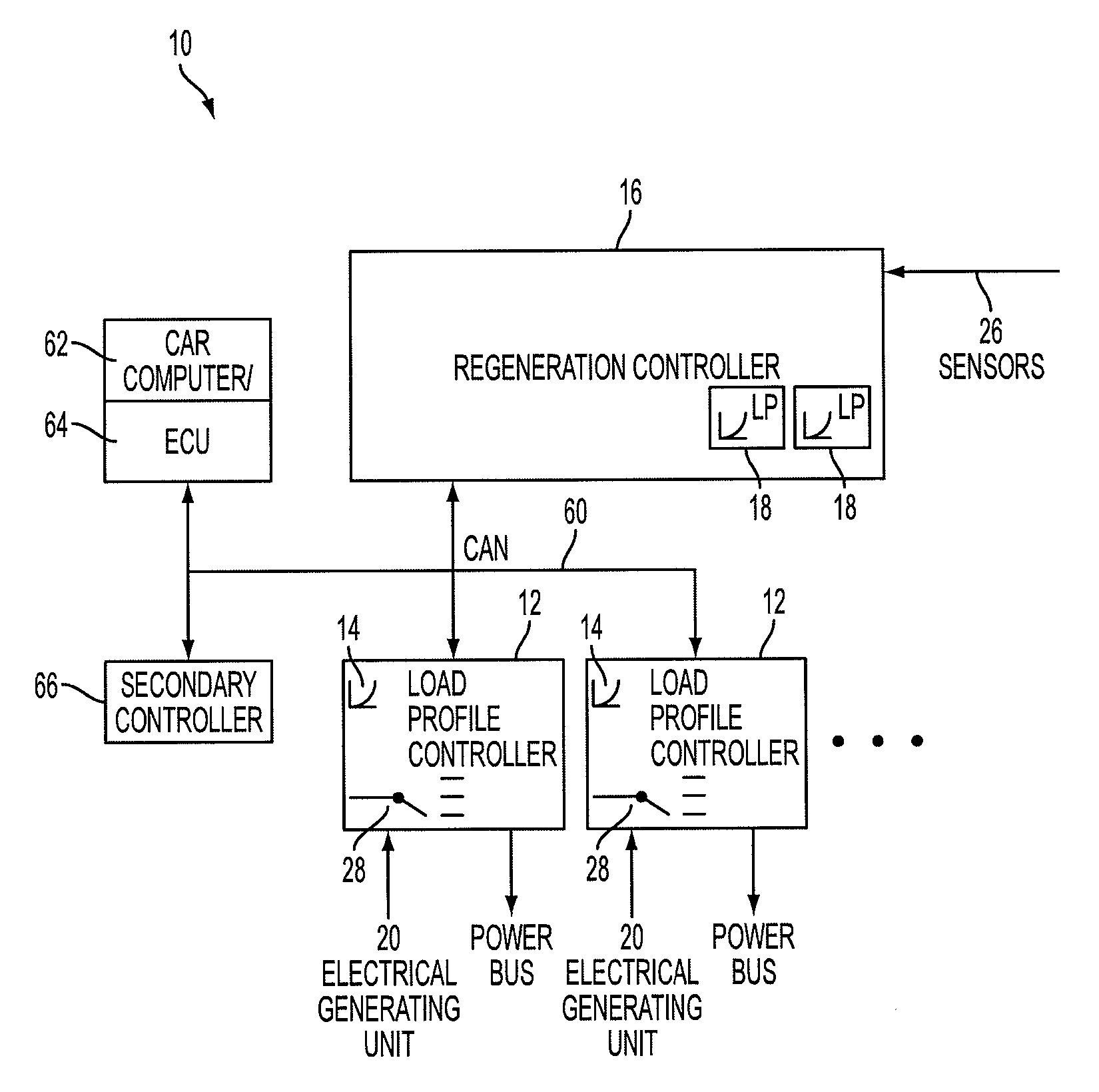
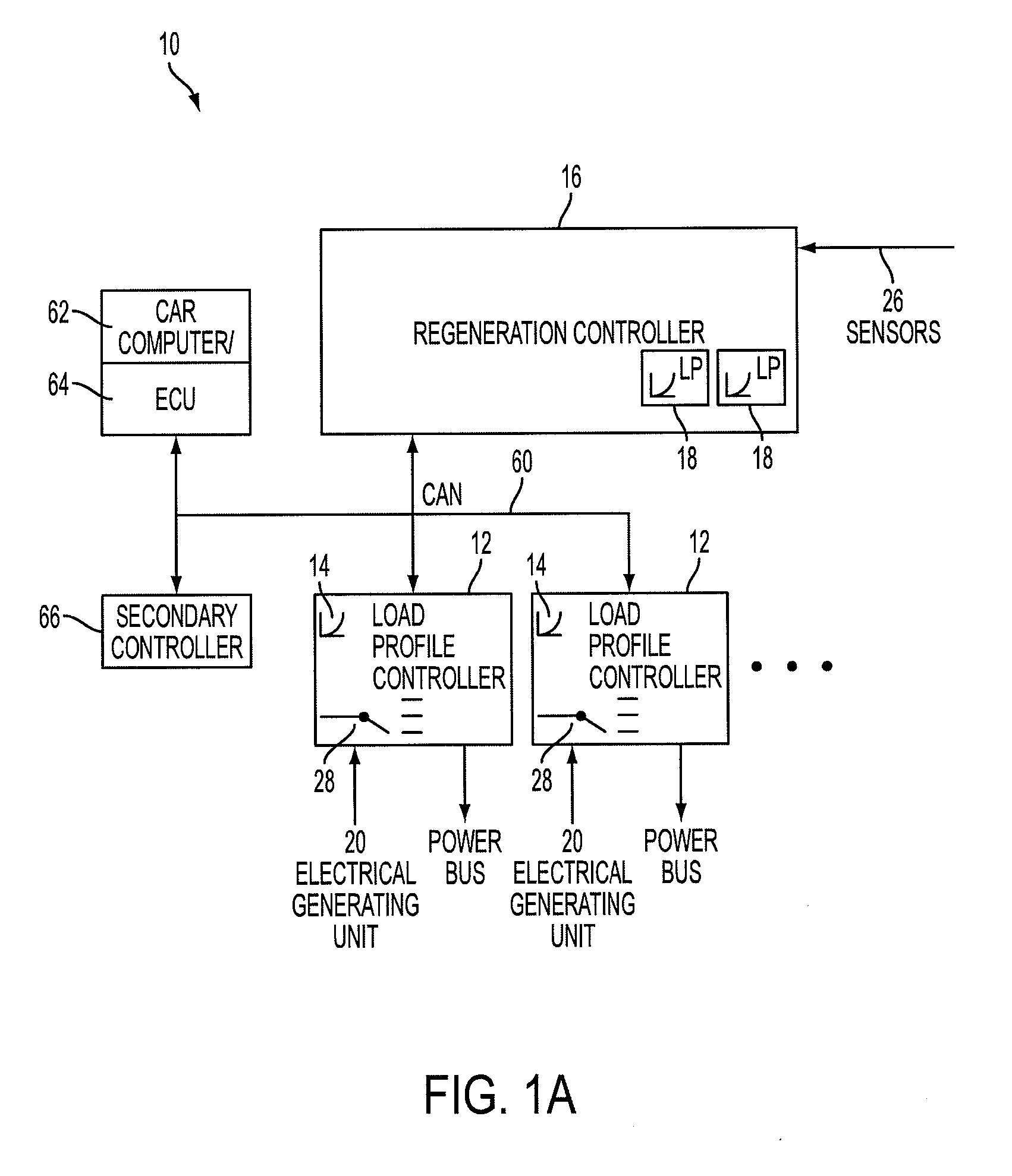
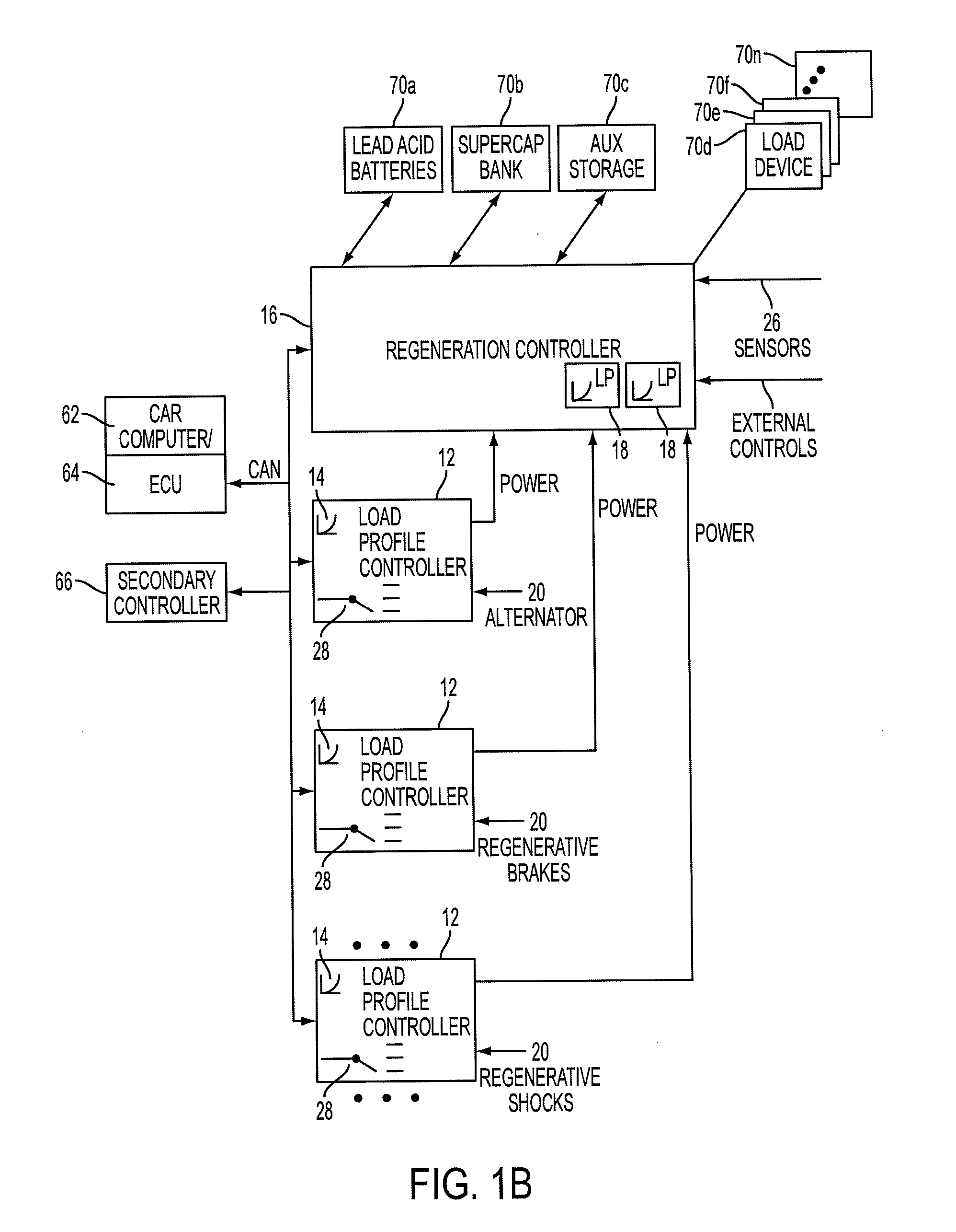
[0030]In accordance with one aspect of the invention, a system that can dynamically provide a variable load on a generator and intelligently distribute generated power to energy consuming devices and / or energy storage devices of an output load is disclosed. In one embodiment, the system can simultaneously provide variable damping of the generator (or other control of a kinematic characteristic of the generator) and independently variable output power to the output load. In an illustrative embodiment, the system includes one or more load profile controllers that employ a switching strategy to dynamically vary the load the generator induces while producing regenerative energy. This switching strategy may allow for a wide dynamic range of configurable kinematic characteristics. Multiple load profile controllers can be used to control multiple generators, and may be linked together via a communications network, such as a vehicle controller area network (CAN) bus, or a time-triggered con...


PUM


Abstract

A device and system that can dynamically provide variable load on a generator and intelligently distribute generated power to loads and energy storage devices is disclosed. One system includes load profile controllers that employ a switching strategy to dynamically vary the load the generator induces while producing regenerative energy. This switching strategy may allow for a wide dynamic range of configurable damping characteristics, as well as decouple generator damping and the system output power. Multiple load profile controllers can be used together via a communications network, such as a vehicle controller area network (CAN) bus. A central regeneration controller or existing electronic control unit (ECU) can issue commands to change damping performance in different load profile controllers. By networking multiple load profile controllers together in either a distributed or centralized manner, the system may allow for intelligent power routing, coordination of multiple energy-generating devices (such as regenerative shocks and brakes), and improved utilization of on-board energy storage devices.

Description

[0001]This application is a continuation in part of U.S. application Ser. No. 12 / 104,800, filed Apr. 17, 2008, and claims the benefit of U.S. Provisional application 61 / 230,145, filed Jul. 31, 2009.BACKGROUND[0002]1. Field[0003]Aspects relate to regenerative energy generator controllers and, more particularly to devices and systems that modulate a load on a generator and / or interconnect multiple power generation devices to a vehicle's power systems.[0004]2. Discussion of Related Art[0005]Modern automobiles such as hybrid electrics, military vehicles, and heavy trucks are increasingly being equipped with regenerative power sources, energy storage devices, and power-consuming equipment. Regenerative power sources such as regenerative shock absorbers have the potential to increase the fuel economy and / or other performance characteristics of these vehicles and in some cases improve ride performance.SUMMARY OF INVENTION[0006]Aspects of the invention relate to integration of regenerative ...

Claims


Application Information

Patent Timeline
Patent Type & Authority Applications(United States)
IPC IPC(8): G06F1/26B60L1/00F03G7/08
CPCB60G13/14B60G2300/60B60K25/10B60L7/003B60L7/18Y02T90/16B60L2250/16B60L2250/30B60L2270/145Y02T10/7283B60L15/2045Y02T10/64Y02T10/72
Inventor ANDERSON, ZACKARY M.MORTON, SEAN C.JACKOWSKI, ZACHARY J.BAVETTA, RYAN
Owner CLEARMOTION INC
Why Eureka
Try Eureka