Noise suppression device and noise suppression method

a technology of noise suppression device and noise suppression method, which is applied in the direction of electrical transducers, instruments, image enhancement, etc., can solve the problems of increasing the number of microphones in proportion to the increase in the number of sound sources, increasing the cost, and difficulty in practical application, so as to achieve the effect of reducing the amount of computation, simplifying the configuration, and increasing the noise suppression capability

Inactive Publication Date: 2010-10-14
TOKYO UNIVERSITY OF SCIENCE
View PDF4 Cites 22 Cited by
  • Summary
  • Abstract
  • Description
  • Claims
  • Application Information

AI Technical Summary

Benefits of technology

[0024]The present invention enables higher noise suppression capability to be achieved by means of a simp...

Problems solved by technology

However, with a method that uses a microphone array, microphones at least equal in number to the number of noise sources are necessary, and therefore the number of microphones inevitably increases in proportion to an increase in the number of sound sources, and the cost increases.
There are also ...

Method used


Image

  • Noise suppression device and noise suppression method
  • Noise suppression device and noise suppression method
  • Noise suppression device and noise suppression method

Examples


embodiment 1

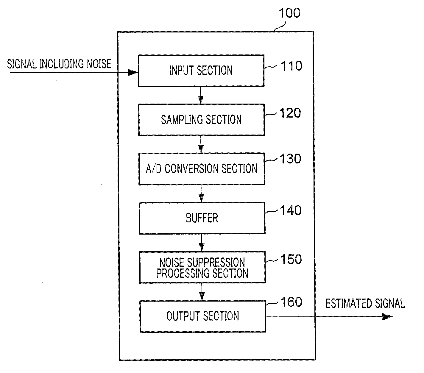
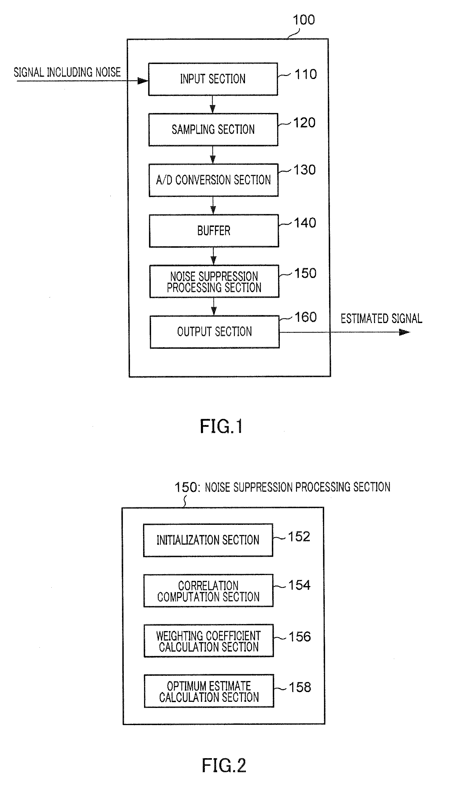
[0082]FIG. 1 is a block diagram showing a configuration of a noise suppression apparatus according to embodiment 1 of the present invention.

[0083]Noise suppression apparatus 100 shown in FIG. 1 has input section 110, sampling section 120, A / D conversion section 130, buffer 140, noise suppression processing section 150, and output section 160.

[0084]Input section 110 has observed information or an observed signal as input. An observed signal is a signal in which a clear signal from an information source (a desired signal) and noise are combined (mixed together). Input section 110 performs input processing on an input analog observed signal, for example, and outputs the signal to sampling section 120. Input processing is, for example, band-limiting processing, automatic gain control processing, and so forth.

[0085]Sampling section 120 performs sampling processing on the input analog observed signal at a predetermined sampling frequency (for example, 16 kHz), and outputs the result to A / ...

embodiment 2

[0261]Embodiment 2 is a case in which a noise suppression apparatus according to embodiment 1 is applied to a fetal heartbeat detection apparatus. “Heartbeat” here is used in the broad sense of movement of the heart, and also includes heart sound, an electrocardiogram, and so forth, for example.

[0262]FIG. 45 is a block diagram showing a configuration of a fetal heartbeat detection apparatus according to embodiment 2 of the present invention.

[0263]Fetal heartbeat detection apparatus 400 shown in FIG. 45 has a computer main unit 410 capable of executing noise suppression processing (invention methods 1 and 2) of embodiment 1, microphone 420, signal input section 430, operation section 440, speaker 450, and display 460.

[0264]Computer main unit 410 has interface section 411, storage section 412 (comprising recording apparatus 413 and main storage memory 414), modem 415, D / A converter 416, noise suppression processing section 417, fetal heartbeat analytical processing section 418, and no...

embodiment 3

[0276]Embodiment 3 is a case in which a noise suppression apparatus according to embodiment 1 is applied to a portable terminal apparatus such as a mobile phone.

[0277]FIG. 46 is a block diagram showing a configuration of a portable terminal apparatus according to embodiment 3 of the present invention. This portable terminal apparatus 500 has a similar basic configuration to that of fetal heartbeat detection apparatus 400 shown in FIG. 45, and therefore identical components are assigned the same reference codes, and descriptions thereof, including options, are omitted here.

[0278]Portable terminal apparatus 500 shown in FIG. 46 has transmission / reception antenna 510 and transmitting / receiving section 520. Transmitting / receiving section 520 performs baseband processing of a speech signal transmitted / received by antenna 510.

[0279]In this portable terminal apparatus 500, an observed speech signal (user speech signal) from microphone 420 is input to signal input section 430, where it is d...


PUM


Abstract

Disclosed is a noise suppression device capable of better noise suppression by means of a simpler structure and with a lighter computational load. A noise suppression device (100) has a noise suppression processor (150) to estimate the required information only from the observed information, which is the required information corrupted by noise. A correlator (154) calculates the correlation of the estimation error when the state quantity, which contains the required information, of the system at time n+1 was estimated from the information until time n or time n+1 for the observed information at only time n. A weighting coefficient calculator (156) uses the correlation calculated by the correlator (154) for the observed information at only time n to calculate the weighting coefficients for specifying the relationships of the optimum estimate of the state quantity at that time based on the information until time n+1, the optimum estimate of the state quantity at time n+1 based on the information until time n, and the estimation error of the observed quantity including the observed information. An optimum estimate calculator (158) uses the weighting coefficients calculated by the weighting coefficient calculator (156) for the observed information only at time n to calculate the optimum estimate of the state quantity at that time based on the information until time n or time n+1.

Description

TECHNICAL FIELD[0001]The present invention relates to a noise suppression apparatus and noise suppression method.BACKGROUND ART[0002]Removing unnecessary information (noise) from observed information (information corrupted by noise and so forth) in which unnecessary information (noise) is mixed in with desired information (a desired signal), and extracting only desired information, is an important technology in the fields of speech and radio communications, imaging, attitude control, recognition, industrial / welfare / medical robotics, and the like, and has been the subject of considerable research and development in recent years.[0003]For example, a method whereby a single microphone is used and a method whereby a microphone array comprising a plurality of microphones is used have been proposed as heretofore known noise suppression methods in the speech field.[0004]However, with a method that uses a microphone array, microphones at least equal in number to the number of noise sources ...

Claims


Application Information

Patent Timeline
IPC IPC(8): G10L21/02H04B15/00G10L15/20G06F17/10G10L21/0208G10L21/0216G10L21/0264G10L25/06
CPCG06T5/002G06T5/003G06T5/50G06T2207/10016G10L2021/02163G06T2207/20182G06T2207/20221G10L21/0208G10L25/06G06T2207/20076
Inventor TANABE, NARIFURUKAWA, TOSHIHIRO
Owner TOKYO UNIVERSITY OF SCIENCE
Why Eureka
Try Eureka