Method for automatically opening door and device for automatically opening and closing door

a technology for automatically opening doors and doors, applied in the direction of hinges, transportation and packaging, wing accessories, etc., can solve the problems of manual opening and closing, easy adverse effects of methods, and difficult or very difficult opening and closing, etc., to achieve simple structure, reduce the number of components involved, and easy to establish large open space

Inactive Publication Date: 2010-10-21
YUKI CORP
View PDF0 Cites 12 Cited by
  • Summary
  • Abstract
  • Description
  • Claims
  • Application Information

AI Technical Summary

Benefits of technology

[0026]Since the present invention is configured as described above, the slide door can be swiftly moved to the opening direction in response to the stepping on to the tread plate. Moreover, since the movement biasing force has been applied toward the closing direction of the slide door, an external force is not necessary to close the door. By using a plurality of slide doors, a large open space can be easily established.
[0027]Moreover, since the number of components involved can be reduced because of the simple structure, high reliability with no trouble is possible. By establishing the angle of inclination appropriately, the biasing force can be easily adjusted. The slide door is able to perform open and close movement along the suspend door rail, and the open door biasing force and closing door biasing force of the door and speed can be easily adjusted.
[0028]Moreover, even when light weight such as about 10 kg is applied, the door can be automatically opened or closed, and the door can be manually moved to the closing direction when locking up the door. Thus, the device for automatically opening and closing the door

Problems solved by technology

Moreover, it has a drawback in that when dust etc. is accumulated at the guide rail due to long use, this method is easily affected adversely.
In addition, it has a dr

Method used


Image

  • Method for automatically opening door and device for automatically opening and closing door
  • Method for automatically opening door and device for automatically opening and closing door
  • Method for automatically opening door and device for automatically opening and closing door

Examples


embodiment 1

[Effect of Embodiment 1]

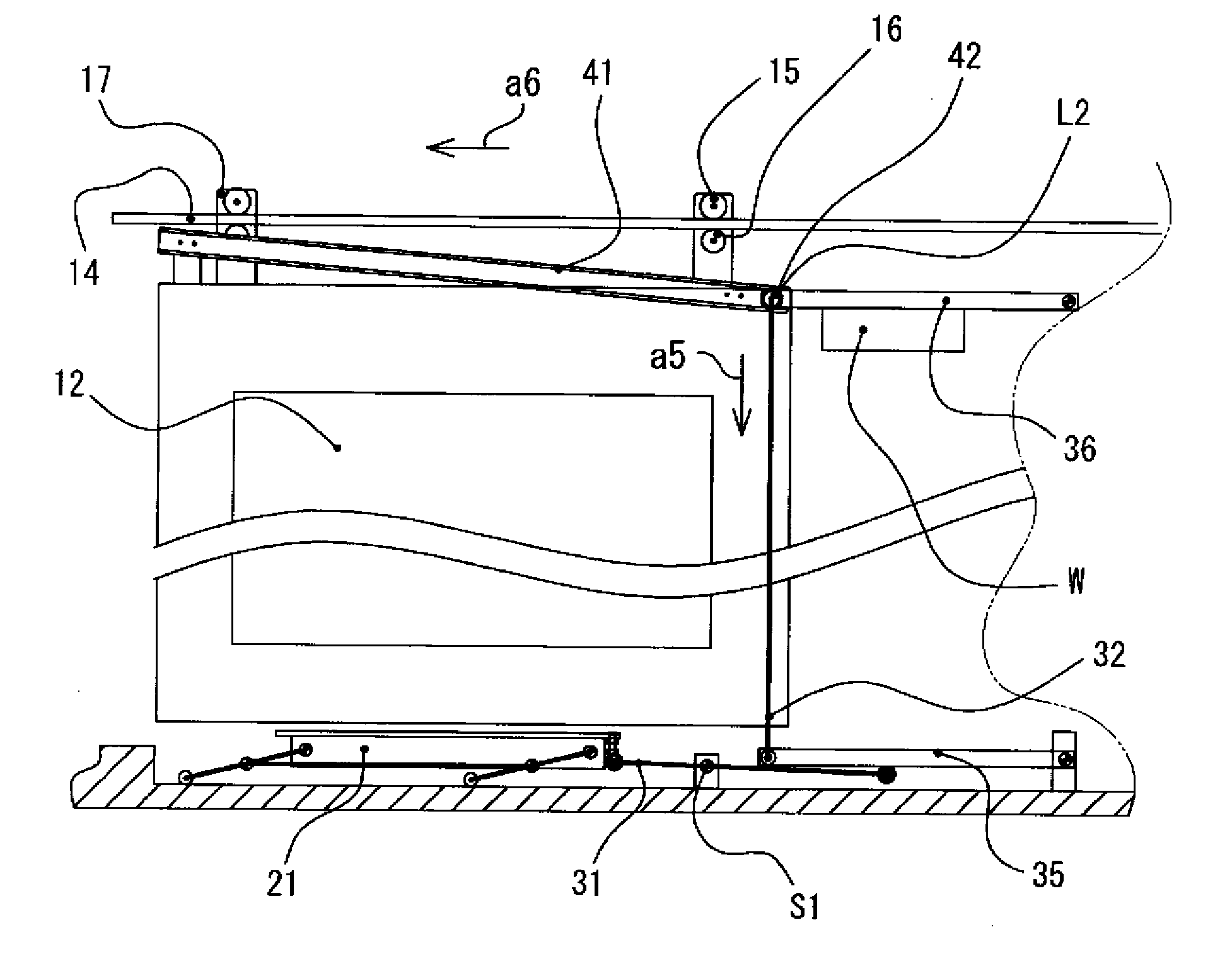
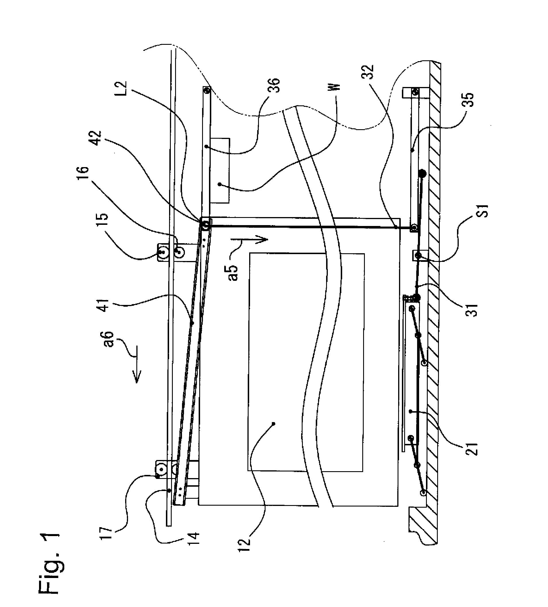
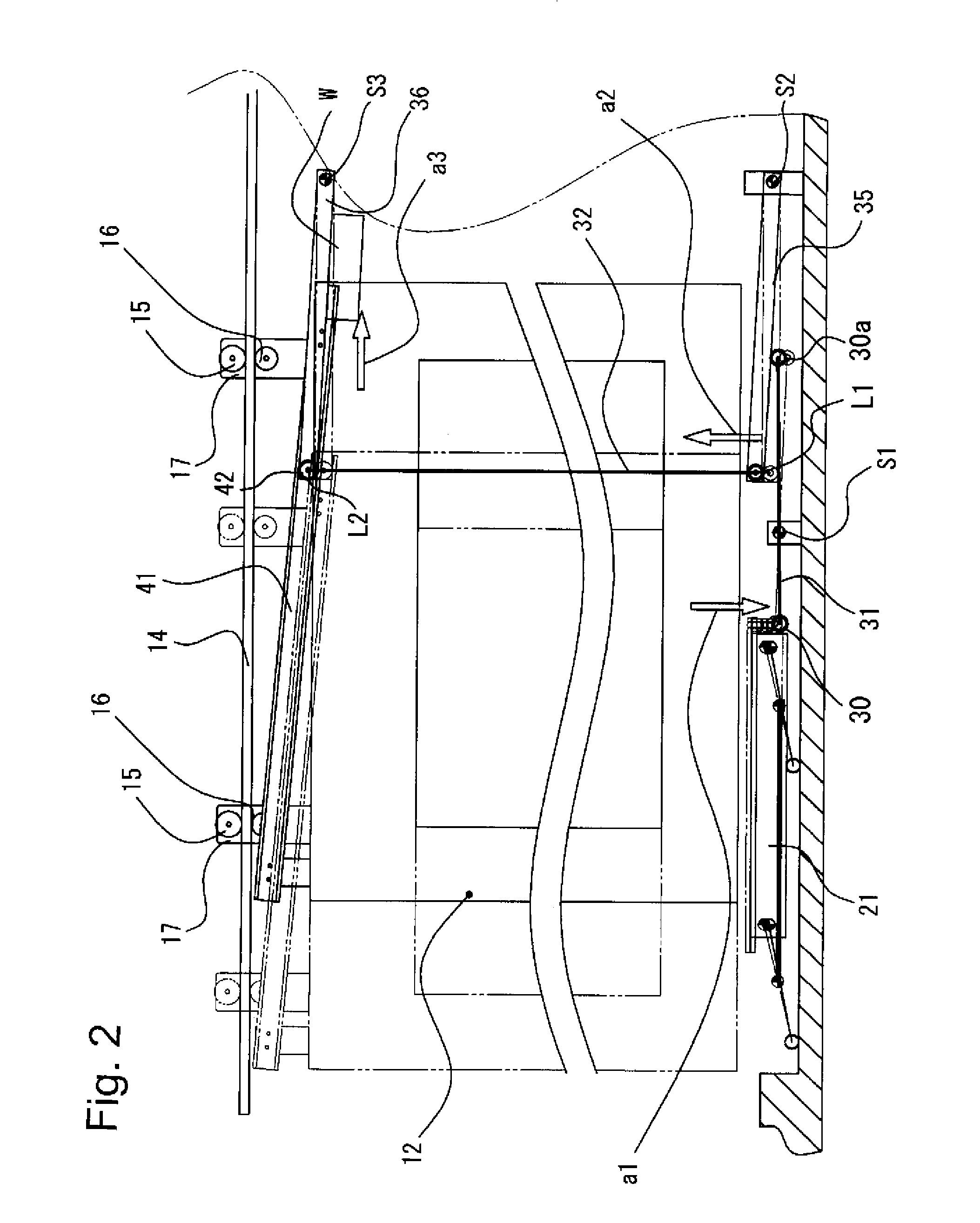
[0107]In the embodiment 1, in the open door condition of FIG. 2, due to the weight of the transmission elongated part 32 and the adjustment W (refer to FIGS. 1 and 2), the transmission elongated part 32 is biased downwardly (arrow a5), which is pressing down the lower surface of the groove of the open door rail41 and biases the slide door 12 to the closing direction (arrow a6). When, as shown in FIG. 3, a weight is applied to the tread plate 21 from the close door condition and the tread plate 21 is depressed (arrow a1), the transmission elongated part 32 is moved upwardly (arrow a2), and the drive rotation body 42 presses up the upper surface of the groove of the open door rail 41. Due to the component force at the contact point, the slide door 12 moves to the opening direction (arrow a3).

[0108]Further, as shown in FIG. 4, due to the pressing-up by the drive rotation body 42, the slide door 12 moves to the completely open condition (arrow a3). Then, when the...

embodiment 2

[Effect of Embodiment 2]

[0120]In the embodiment 2, in the closed door condition shown in FIG. 9, the weight of the transmission elongated part and the adjustment weight W bias (arrow a7) the transmission elongated part 32 downwardly. The lower surface of the groove of the supplementary rail 41b is pressed down and thus the slide door 12 is biased (arrow a6) to the closing direction. Starting from this closed condition, when weight is applied (arrow a1) to the tread plate 21 as shown in FIG. 10, the transmission elongated part 32 is pressed up (arrow a2) as shown in FIG. 10. Thus, the drive rotation body 42 presses up the open door rail 41. Due to the component force at the contact point, the slide door 12 is moved (arrow a3) toward the opening direction.

[0121]At the same time, the supplementary rotation body 42b moves up along the slant of the upper surface of the supplementary rail 41b and slides to the opened direction (arrow a3) as shown in FIG. 11. At this time, the tension spri...

embodiment 3

[0123]FIG. 13 is a partial front view that schematically shows a part of the configuration of the embodiment 3 of the present embodiment. FIGS. 14-16 are partial front views showing the operational condition of the embodiment 3.

[0124]The device for automatically opening and closing a door of the embodiment 3 comprises, at the upper part, a suspend door rail 140 that inclines downwardly toward the closing direction of the slide door 120, a runner roller 150 as a door support body of the hung door, a slide door 120 that is fixed to a suspend door rail 140 through the runner roller 150, an open door rail 410 that is fixed to the slide door 120 with an inclination opposite to that of the suspend door rail 140, a tread plate 21, an open door mechanism that moves up and down the drive rotation body 420 by coordinating with the tread plate 21, and weight W fixed to the tread plate 210.

[0125]The open door mechanism applies a pressing force to the open door rail by means of the drive rotatio...


PUM


Abstract

A door opening and closing device for a slide door, which can be horizontally open and close the slide door by application of a light load and which can be constructed and maintained at low costs. The door opening and closing device has a transmission mechanism for converting through a lever (31) the amount of settlement of a tread plate (21) placed on floor surfaces at positions in front and back of the slide door (12), into a predetermined displacement amount. The tread plate (21) is weight-wise balanced such that the transmission mechanism and settlement of the tread plate due to the weight of an adjustment weight (W) causes the tread plate (21) to float through the lever (31). Up-down movement of the long transmission member (32) presses a drive rotation body (42) to an open door rail (41), and a component force of the pressing force allows the slide door (12) to be opened by application of a light load.

Description

FIELD OF THE INVENTION[0001]The present invention relates to a method for automatically opening a door to open a slide door of a doorway by applying a bodyweight of a human stepping on, and to a device for automatically opening and closing a door using the same.BACKGROUND OF THE INVENTION[0002]There have been many applications with respect to a mechanism for opening and closing a slide door of a doorway by using a load displacement caused by a load of stepping-on of a human body as a source of power without using additional source of power such as electric motor.[0003]For example, Japanese Laid Open Utility Number HOG-37482 discloses a method (incline method) that uses an amount of displacement caused by a stepping on to appropriately incline a guide rail positioned on an upper or a lower portion of a slide door by a link mechanism toward a desired moving direction, and thereby slidably moving the slide door along the incline.[0004]However, the incline method noted above has a drawb...

Claims


Application Information

Patent Timeline
IPC IPC(8): E05F11/54E06B3/44
CPCE05D15/06E05F1/02E05F1/025E05F1/046E05F13/04E05Y2900/132E05Y2201/638E05Y2201/684E05Y2201/688E05Y2600/31E05Y2201/604E05F11/54E05Y2201/676E05D5/0246E06B3/46
Inventor NAKANO, YASUO
Owner YUKI CORP
Why Eureka
Try Eureka