LED lamp

a technology of led lamps and leds, which is applied in the direction of discharge tubes luminescnet screens, semiconductor devices for light sources, lighting and heating apparatus, etc., can solve the problems of high beam of leds, inability of the illumination device to obtain the desired illumination area, and uneven light emitted by the leds

Inactive Publication Date: 2010-10-21
FU ZHUN PRECISION IND SHENZHEN +1
View PDF1 Cites 69 Cited by
  • Summary
  • Abstract
  • Description
  • Claims
  • Application Information

AI Technical Summary

Benefits of technology

[0005]For an LED, about eighty percents of the power consumed thereby is converted into heat. Therefore, a heat dissipation device is necessary for timely and adequately removing the heat generated by the LED. Generally, the LED lamp includes a plurality of LEDs. The LEDs are arranged on a flat surface whereby an illumination area of the LEDs is limited. Thus, the illumination device cannot obtain a desired illumination area. Further, the light emitted by the LEDs is not evenly distributed due to the directive reflection property of the LEDs. Further, high beam of the LEDs has blinding effect. Direct glare coming straight from the LEDs causes discomfort and annoyance.
[0005]For an LED, about eighty percents of the power consumed thereby is converted into heat. Therefore, a heat dissipation device is necessary for timely and adequately removing the heat generated by the LED. Generally, the LED lamp includes a plurality of LEDs. The LEDs are arranged on a flat surface whereby an illumination area of the LEDs is limited. Thus, the illumination device cannot obtain a desired illumination area. Further, the light emitted by the LEDs is not evenly distributed due to the directive reflection property of the LEDs. Further, high beam of the LEDs has blinding effect. Direct glare coming straight from the LEDs causes discomfort and annoyance.
[0005]For an LED, about eighty percents of the power consumed thereby is converted into heat. Therefore, a heat dissipation device is necessary for timely and adequately removing the heat generated by the LED. Generally, the LED lamp includes a plurality of LEDs. The LEDs are arranged on a flat surface whereby an illumination area of the LEDs is limited. Thus, the illumination device cannot obtain a desired illumination area. Further, the light emitted by the LEDs is not evenly distributed due to the directive reflection property of the LEDs. Further, high beam of the LEDs has blinding effect. Direct glare coming straight from the LEDs causes discomfort and annoyance.
[0002]The present disclosure relates to an LED (light emitting diode) lamp, and particularly to an LED lamp with a high heat dissipating efficiency and an even illumination intensity.

Problems solved by technology

Thus, the illumination device cannot obtain a desired illumination area.
Further, the light emitted by the LEDs is not evenly distributed due to the directive reflection property of the LEDs.
Further, high beam of the LEDs has blinding effect.
Direct glare coming straight from the LEDs causes discomfort and annoyance.

Method used


Image

  • LED lamp
  • LED lamp
  • LED lamp

Examples


first embodiment

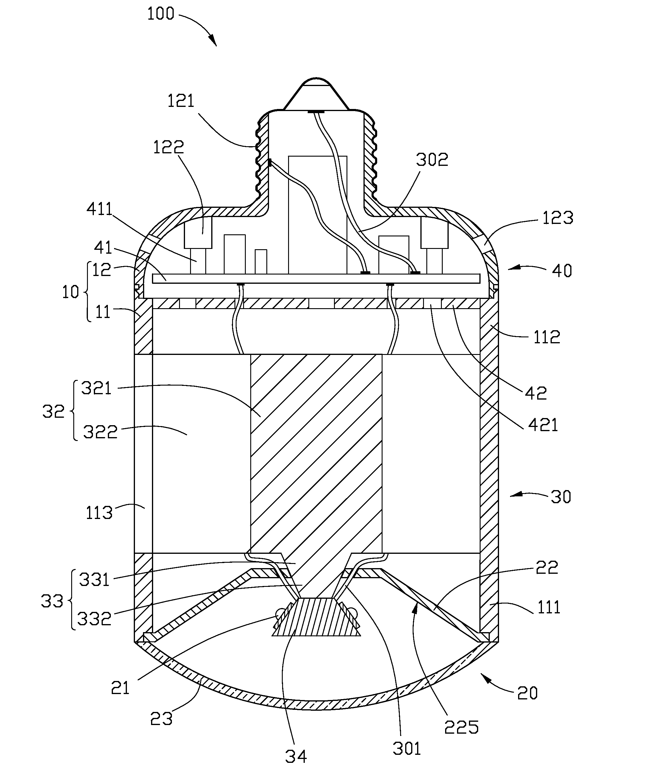
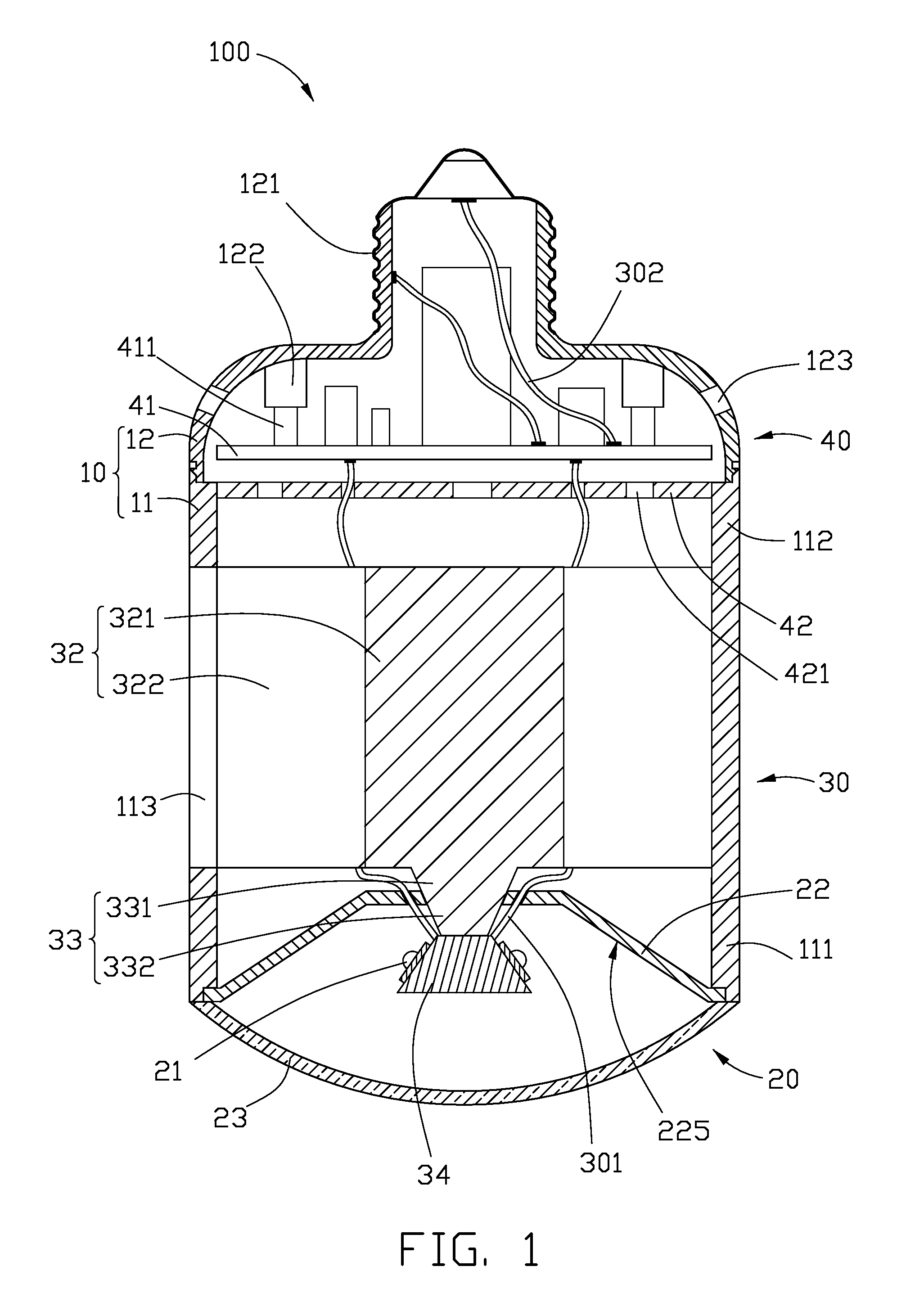
[0020]Referring to FIG. 1, an LED lamp 100 includes a hollow lamp housing 10, an optical part 20, a heat dissipation part 30, and an electrical part 40. The LED lamp 100 is substantially cylindrical. The optical part 20 is arranged at a front end of the LED lamp 100. The electrical part 40 is arranged at a rear end of the LED lamp 100. The heat dissipation part 30 is located between the optical part 20 and the electrical part 40. The optical part 20, the heat dissipation part 30 and the electrical part 40 are received in the lamp housing 10.

[0021]The lamp housing 10 includes a front shell 11 and a rear shell 12 connected to the front shell 11. The front shell 11 is a hollow cylinder, and has a front end 111 and an opposite rear end 112 connecting with the rear shell 12. The optical part 20 is arranged at the front end 111 of the front shell 11. The heat dissipation part 30 is arranged in the front shell 11, while the electrical part 40 is arranged in the rear shell 12. The rear she...

second embodiment

[0040]Referring to FIG. 8, a light engine of an LED lamp is illustrated. The light engine is cooperatively formed by the heat sink 32, the heat conducting member 33 and the mounting seat 34. Except the following differences, the light engine of the present embodiment is essentially the same as the light engine of the LED lamp 100 shown in FIG. 1. In the present embodiment, a blind hole 324 is axially defined in a rear portion of the solid base 321 in order to increase the heat exchange surface of the heat sink 32. The blind hole 324 extends vertically from the rear portion of the solid base 321 adjacent to the electrical part 40 toward a front portion of the solid base 321 adjacent to the optical part 20.

[0041]A plurality of air venting holes 325 are radially defined in the front portion of the solid base 321. The air venting holes 325 communicate a bottom of the blind hole 324 with an outside of the solid base 321. In operation, air in the blind hole 324 is heated by the heat of t...

third embodiment

[0042]Referring to FIGS. 9-10, an LED lamp 100a is illustrated. The difference between the present LED lamp 100a and the LED lamp 100 illustrated in FIG. 1 lies in the heat dissipation part 30a. In the present embodiment, the heat dissipation part 30a further includes a cooling fan 35 provided between the electrical part 40 and the heat sink 32, and a heat conducting member of the heat dissipation part 30a is a heat pipe 33a. It is well known in the art that a heat pipe is a sealed hollow pipe body receiving working fluid therein and containing a wick structure disposed on an inner wall of the pipe body.

[0043]The heat pipe 33a transfers heat under phase change of working fluid hermetically contained therein. The heat pipe 33a is linear-shaped, and includes a front evaporating section 331 a connecting with the mounting seat 34c and a rear condensing section 332a connecting with the heat sink 32. The heat sink 32 defines axially a first receiving hole 326 in the solid base 321 thereo...


PUM


Abstract

An LED lamp includes a hollow lamp housing, a front optical part, a rear electrical part, and a middle heat dissipation part. The heat dissipation part includes a heat sink, a mounting seat in front of the heat sink, and a heat conducting member connecting the mounting seat with the heat sink. The lamp housing defines a plurality of air exchanging holes corresponding to the fins. The mounting seat includes a small top surface, an opposite large bottom surface, and a plurality of sloping heat absorbing surfaces between the top surface and the bottom surface. The optical part includes a plurality of light sources arranged on the heat absorbing surfaces, a light reflector located between the heat sink and the mounting seat and surrounding the heat conducting member, an optical lens located in front of the light reflector and the mounting seat.

Description

BACKGROUND[0001]1. Technical Field[0002]The present disclosure relates to an LED (light emitting diode) lamp, and particularly to an LED lamp with a high heat dissipating efficiency and an even illumination intensity.[0003]2. Description of Related Art[0004]In recent years, LEDs are preferred for use in LED lamps rather than CCFLs (cold cathode fluorescent lamps) and other traditional lamps due to their excellent properties, including high brightness, long lifespan, directivity, and etc.[0005]For an LED, about eighty percents of the power consumed thereby is converted into heat. Therefore, a heat dissipation device is necessary for timely and adequately removing the heat generated by the LED. Generally, the LED lamp includes a plurality of LEDs. The LEDs are arranged on a flat surface whereby an illumination area of the LEDs is limited. Thus, the illumination device cannot obtain a desired illumination area. Further, the light emitted by the LEDs is not evenly distributed due to the...

Claims


Application Information

Patent Timeline
Patent Type & Authority Applications(United States)
IPC IPC(8): H01J61/52
CPCF21V7/0008F21V29/89F21V29/004F21V29/006F21V29/02F21Y2101/02F21K9/137F21K9/1375F21Y2111/007H01L2924/0002F21V19/0055F21V29/83F21V29/677F21V29/77H01L2924/00F21K9/23F21K9/233F21Y2115/10F21Y2107/40F21V29/51
Inventor LIU, TAY-JIANQIAN, JIAN-BING
Owner FU ZHUN PRECISION IND SHENZHEN
Why Eureka
Try Eureka