Battery pack, battery charger, and battery pack system

Active Publication Date: 2010-10-21
KK TOSHIBA
View PDF6 Cites 25 Cited by
  • Summary
  • Abstract
  • Description
  • Claims
  • Application Information

AI Technical Summary

Benefits of technology

[0016]Namely, the battery pack calculates the optimal charging current values and specifies the charging current values with respect to the battery charger, thereby contr

Problems solved by technology

However, the conventional battery charger described in PTL 1 did not include a method in which a battery pack could specify a charging current with respect to a batte

Method used


Image

  • Battery pack, battery charger, and battery pack system
  • Battery pack, battery charger, and battery pack system
  • Battery pack, battery charger, and battery pack system

Examples


Example

Example 1

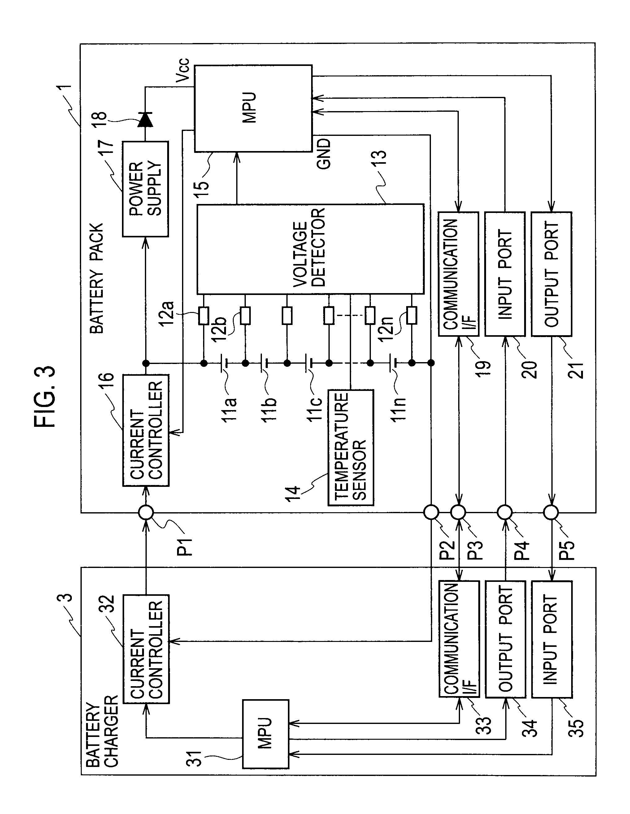
[0030]FIG. 3 is a circuit configuration diagram of a battery pack system of Example 1. In FIG. 3, the battery pack system includes a rechargeable battery pack 1, and a battery charger 3 for recharging rechargeable batteries in the battery pack 1.

[0031]The battery pack system monitors charged conditions of the batteries by a voltage detector for detecting voltages of the respective batteries in the battery pack 1 and a temperature sensor for sensing temperatures of the respective batteries, calculates current values in this point for recharging the batteries by a charging current calculator according to the monitored data, and transmits the current values to the battery charger via a communication I / F, thereby controlling charging currents.

[0032]The battery pack 1 includes a plurality of rechargeable batteries 11a to 11n (hereinafter, “n” means that an arbitrary number of one or more batteries are connected) connected in series, a plurality of resistors 12a to 12n (hereinaft...

Example

Example 2

[0042]FIG. 4 is a circuit configuration diagram of a battery pack system of Example 2. In FIG. 4, the battery pack system further includes a diode 23, and a power supply 22 that is activated by a battery charger condition signal input from the battery charger 3 via the input port 20 and supplies a current to the MPU 15 via the diode 23 to operate the MPU 15, in addition to the configuration of the battery pack system of Example 1 illustrated in FIG. 3.

[0043]Note that, in Example 2, the same components as Example 1 are indicated by the same numerals, and explanations thereof are omitted.

[0044]In the configuration of Example 2 as described above, the power supply 22 is activated by the battery charger condition signal input from the battery charger 3 via the input port 20, and supplies the current to the MPU 15 via the diode 23 to operate the MPU 15. Therefore, the power supply 22 operates the MPU 15 in the battery pack 1 even when the battery charger 3 is not in a state supp...

Example

Example 3

[0045]FIG. 5 is a circuit configuration diagram of a battery pack system of Example 3. In FIG. 5, the battery pack system includes a different component, an MPU 31a in a battery charger 1b, from the battery pack system of Example 2 illustrated in FIG. 4.

[0046]Note that, in Example 3, the same components as Example 2 illustrated in FIG. 4 are indicated by the same numerals, and explanations thereof are omitted.

[0047]The communication I / F 19 in a battery pack 1b outputs a status signal of the battery pack 1b in the MPU 15 to a communication I / F 33 in the battery charger 3b. Then, the output port 21 in the battery pack 1b outputs a charge available condition signal of the battery pack 1b to the input port 35 in the battery charger 3b.

[0048]The communication I / F 33 in the battery charger 3b obtains the status signal of the battery pack 1 from the communication I / F 19. Then, the input port 35 inputs the charge available condition signal of the battery pack 1 from the output por...


PUM


Abstract

A battery pack includes: a plurality of rechargeable batteries (11a to 11n) connected in series or in parallel; a voltage detector (13) for detecting voltages of the respective batteries; a calculator (15) for calculating optimal charging current values based on the voltages of the respective batteries detected by the voltage detector so as to recharge the respective batteries; and a communicator (19) for transmitting the charging current values calculated by the calculator to a battery charger (3).

Description

TECHNICAL FIELD[0001]The present invention relates to a rechargeable battery pack, a battery charger, and a rechargeable battery pack system, which are used for a hybrid vehicle, a running power source for an electrically power assisted cycle, and the like. More specifically, the present invention relates to an interface between the rechargeable battery pack and the battery charger, and a technique for a control system of the battery charger.BACKGROUND ART[0002]In a circuit configuration of a conventional battery pack system illustrated in FIG. 1, a battery charger 3e had controlled a charging voltage and a charging current so as to supply the charging voltage and the charging current to a battery pack 1e. For example, as illustrated in FIG. 2, a battery charge had been controlled by a method of a CCCV charge, i.e. recharging at a set current Is in a constant current charge period T1, and recharging at a set voltage Vs in a constant voltage charge period T2.[0003]Thus, the conventio...

Claims


Application Information

Patent Timeline
IPC IPC(8): H02J7/00H02J7/02H02J7/04
CPCH01M10/443H01M10/486Y02B40/90H02J2007/0098H02J7/0086H01M10/4257H02J7/00036H02J7/00047Y02E60/10H02J7/007182Y02B40/00
Inventor ASHIDA, KAZUHIDE
Owner KK TOSHIBA
Why Eureka
Try Eureka