
System and Method for Improved Forensic Analysis

a technology of forensic analysis and system, applied in the field of forensic analysis, can solve the problems of difficult interpretation or confidence of graphs by other non-experts, the method is extremely sensitive, and the use of finite materials, so as to achieve the effect of providing additional clarity over the single snapshot imag

Inactive Publication Date: 2010-10-21
CHEMIMAGE TECH
View PDF9 Cites 12 Cited by
  • Summary
  • Abstract
  • Description
  • Claims
  • Application Information

AI Technical Summary

Benefits of technology

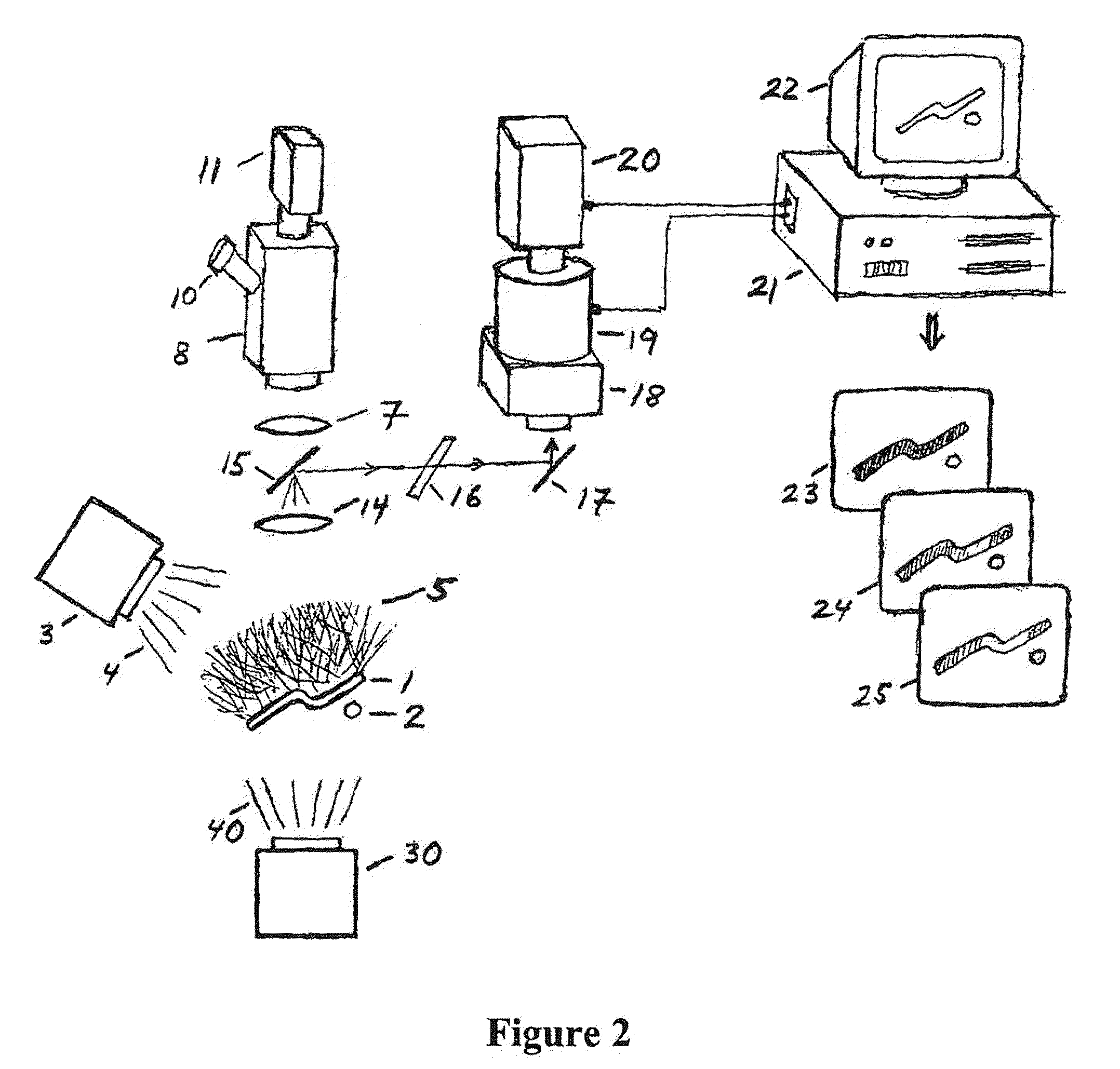
[0012]In the multi-view approach of the present invention, the reflection, absorption, emission or scattering of this incident illumination at a plurality of wavelengths over the entire image of the forensic specimen is examined to create multiple views of the specimen. No tuning of the incident radiation is required to perform this analysis. The multiple views are captured digitally and computer processed to show how the forensic material signals vary at any point (pixel) in the sample over the entire filed of view. These chemical spatial variations can then be processed with a computer to be identified and mapped onto the original image, thereby providing additional clarity over the single snapshot image.

Problems solved by technology

Many of these methods are extremely sensitive and require finite material for their use that is consumed as part of the analysis process.
However, the principles of such methods and the resulting graphs can be difficult for other non-experts to interpret or place confidence in.
Thus, when presenting this evidence in courtrooms, such techniques may not be sufficiently understood to provide convincing or compelling evidence.
Despite the existence of many advanced scientific techniques and analysis methods that are very sophisticated, many such techniques may not be understood by non-specialists, and may thereby raise some doubts as to its validity.
One difficulty with systems of the prior art is their relative lack of dynamic range and resolution, making it difficult to clearly differentiate small, subtle or minute variations over the forensic sample.
Prior art systems produce a single image at a given wavelength or set of wavelengths of emitted radiation, making it impossible to view or obtain data from minute portions or different regions of the overall sample if the emitted radiation varies slightly within the sample or compared to the background substrate or sample matrix.

Method used


Image

  • System and Method for Improved Forensic Analysis
  • System and Method for Improved Forensic Analysis
  • System and Method for Improved Forensic Analysis

Examples


Embodiment Construction

[0027]Reference will now be made in detail to the preferred embodiments of the present invention, examples of which are illustrated in the accompanying drawings. Wherever possible, the same reference numbers will be used throughout the drawings to refer to the same or like parts.

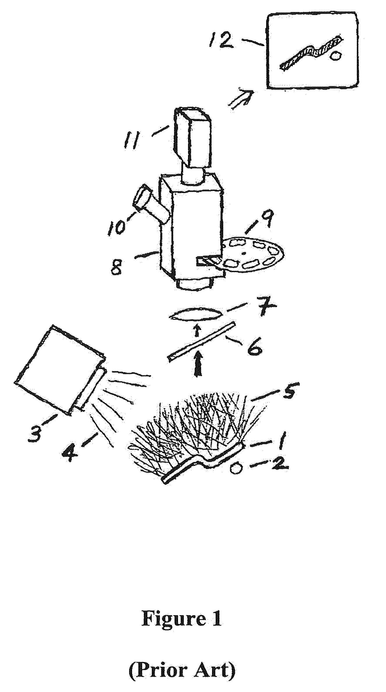
[0028]FIG. 1 shows a general schematic of a typical prior art forensic analysis system. The specimen 1, and reference sample 2, nearby specimen 1 are illuminated with radiation 4 by light source 3, which produces radiation 5, which is reflected from or emitted by specimen 1, and reference sample 2. Light source 3 may or may not be tunable to enhance or accentuate certain features as viewed through the scope or on the sample itself. Usually, the background near the specimen or a calibration object serves as the reference for many measurements. Reflected or emitted radiation 5 may be treated by a conditioning filter 6, and focused via a lens 7, into an optical housing 8, for image capture. In many cases, condi...


PUM


Abstract

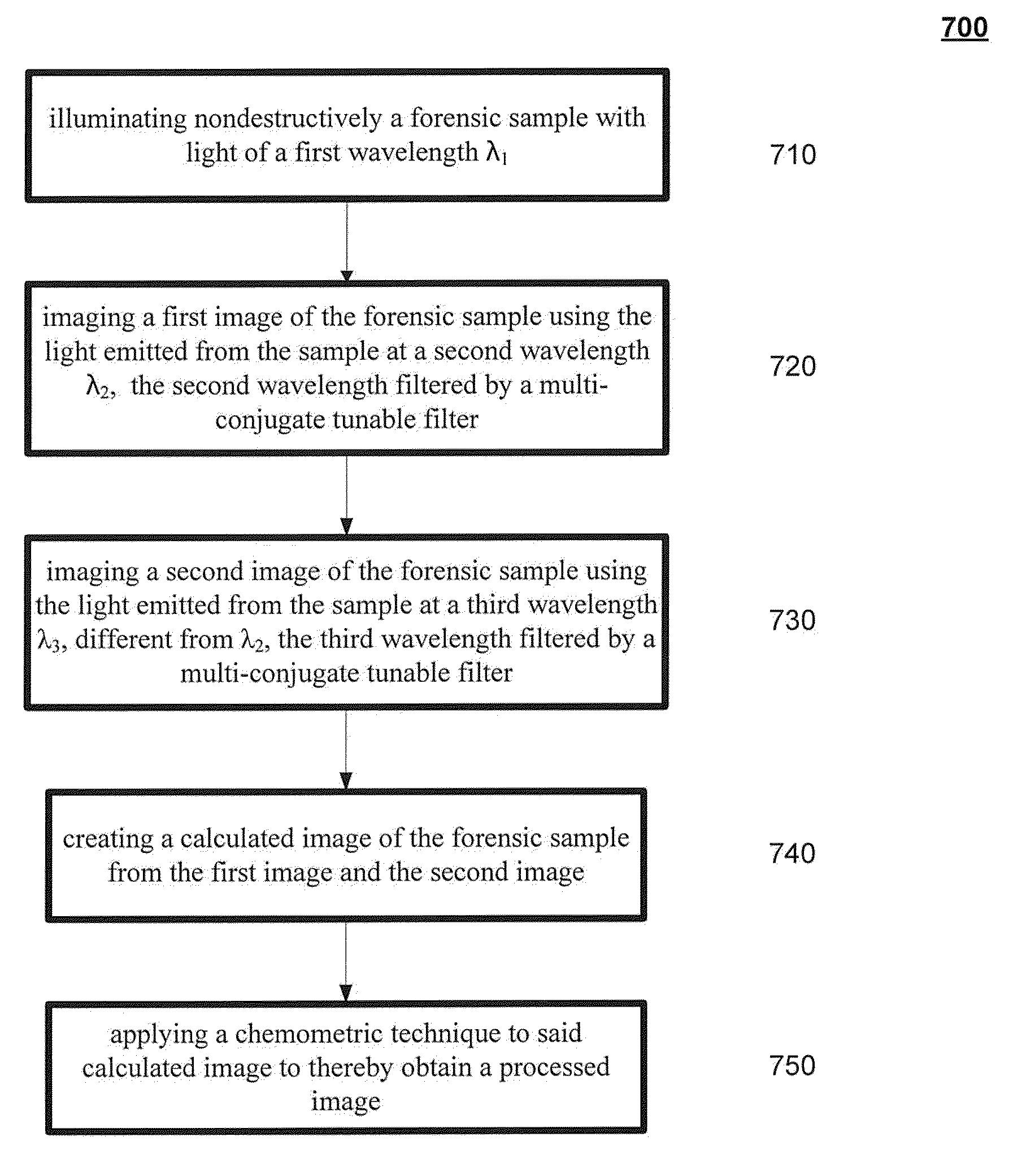
A system and method for analyzing a forensic sample. A forensic sample is illuminated nondestructively with light of a first wavelength λ1. A first image of the forensic sample is imaged using light emitted at a second wavelength λ2, the second wavelength filtered by a multi-conjugate tunable filter. A second image of the forensic sample is imaged using the light emitted from the sample at a third wavelength λ3, different from λ2, the third wavelength filtered by a multi-conjugate tunable filter. A calculated image of the forensic image is then created from the first image and the second image. The disclosure also provides for obtaining a processed image by applying a chemometric technique to the calculated image and for identifying the sample as a known forensic material by searching a reference database for a match to either the calculated image or the processed image.

Description

REFERENCE TO RELATED APPLICATIONS[0001]This application is a continuation-in-part of U.S. patent application Ser. No. 12 / 243,683, entitled “Method for Improved Forensic Analysis,” filed on Oct. 1, 2008, which itself is a continuation of U.S. patent application Ser. No. 10 / 698,243, entitled “Method for Improved Forensic Analysis,” filed on Oct. 31, 2003, which itself claims priority pursuant to 35 U.S.C. §119(e) to U.S. Provisional Application No. 60 / 422,604, filed Oct. 31, 2002. All of these patents and applications are hereby incorporated by reference in their entireties.FIELD OF THE INVENTION[0002]The present invention relates to the field of forensic analysis and, more specifically, to the use of multi-view digital imaging of forensic samples at multiple reflected, scattered, emitted, transmitted or absorbed wavelengths to provide new, detailed information to distinguish and differentiate forensic materials and samples. This method allows more subtle forensic features to be obser...

Claims


Application Information

Patent Timeline
IPC IPC(8): G06T7/00H04N7/18G06V10/143
CPCG06K9/00013G06K9/2018G06T2207/30176G06T5/50G06T2207/10152G06K2009/00946G06V40/155G06V10/143
Inventor TREADO, PATRICKEXLINE, DAVIDWOLFE, JULIANNE
Owner CHEMIMAGE TECH
Learn More