Method of Placing a Substrate, Method of Transferring a Substrate, Support System and Lithographic Projection Apparatus

a technology of lithographic projection apparatus and substrate, applied in the direction of optical devices, instruments, photomechanical devices, etc., can solve problems such as overlay errors, and achieve the effects of reducing overlay errors, improving substrate placement, and high component density

Active Publication Date: 2010-10-21
ASML NETHERLANDS BV
View PDF12 Cites 7 Cited by
  • Summary
  • Abstract
  • Description
  • Claims
  • Application Information

AI Technical Summary

Benefits of technology

[0009]With the continual desire to image ever smaller patterns to create device with higher component densities, there is press...

Problems solved by technology

Consequently, an overl...

Method used


Image

  • Method of Placing a Substrate, Method of Transferring a Substrate, Support System and Lithographic Projection Apparatus
  • Method of Placing a Substrate, Method of Transferring a Substrate, Support System and Lithographic Projection Apparatus
  • Method of Placing a Substrate, Method of Transferring a Substrate, Support System and Lithographic Projection Apparatus

Examples


first embodiment

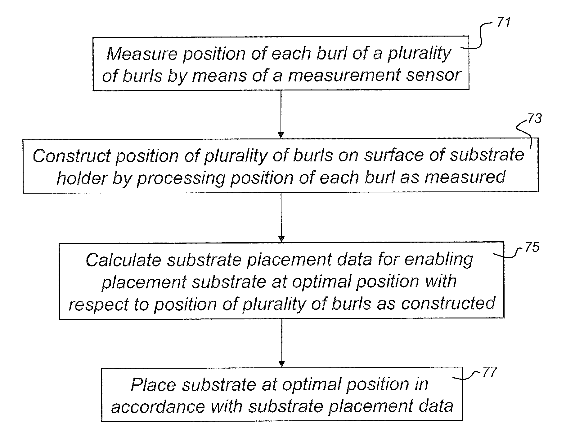
[0024]FIG. 4 schematically depicts a flow chart of a method of placing a substrate onto a surface of a substrate holder according to the invention.

second embodiment

[0025]FIG. 5 schematically depicts a flow chart of a method of placing a substrate onto a surface of a substrate holder according to the invention.

third embodiment

[0026]FIG. 6 schematically depicts a flow chart of a method of placing a substrate onto a surface of a substrate holder according to the invention.

[0027]FIG. 7a schematically depicts a top view of a substrate holder comprising a surface provided with a plurality of burls.

[0028]FIG. 7b schematically depicts a top view of the substrate holder of FIG. 7a on top of which a substrate is placed.


PUM


Abstract

A method of placing a substrate onto a surface of a substrate holder, in which the surface is provided with a plurality of burls. Substrate placement data for allowing placement of the substrate at a certain position with respect to a position of the plurality of burls on the surface of the substrate holder is calculated. The substrate is placed at the certain position in accordance with the substrate placement data. The certain position may be based on the position at which placement would result in a minimized overlay error or may be based on the position at which placement would result in minimized substrate deformation.

Description

CROSS REFERENCE TO RELATED APPLICATIONS[0001]This application is a continuation-in-part of U.S. application Ser. No. 12 / 248,586, filed Oct. 9, 2008, which claims the benefit under 35 U.S.C. §119(e) to U.S. Provisional Application No. 60 / 960,699, filed Oct. 10, 2007, which are both incorporated by reference herein in their entireties.BACKGROUND[0002]1. Field of the Invention[0003]The present invention relates to a method of placing a substrate onto a surface of a substrate holder and a computer readable medium comprising computer executable code, which, when loaded on a computer assembly, enables the computer assembly to control such a method. The invention further relates to a method of transferring a substrate from a first substrate holder to a second substrate holder by means of a transfer unit on the basis of transfer data available thereto, as well as to a computer readable medium comprising computer executable code, which, when loaded on a computer assembly, enables the compute...

Claims


Application Information

Patent Timeline
IPC IPC(8): G03B27/58
CPCG03F7/70633G03F7/70783G03F7/707
Inventor ALBERTI, JOZEF AUGUSTINUS MARIAVAN NUNEN, GERARDUS PETRUS MATTHIJSGROENSMIT, FRANS ERIKCOMPEN, RENE THEODORUS PETRUSVAN DEN HEUVEL, MARCO ADRIANUS PETER
Owner ASML NETHERLANDS BV
Why Eureka
Try Eureka