Overlay Accuracy Correction Method

A technology for overlay accuracy and overlay error, which is applied to microlithography exposure equipment, instruments, and photoengraving techniques for patterned surfaces, etc., can solve problems such as large overlay errors, improve overlay accuracy and reduce overlay The effect of engraving errors

Active Publication Date: 2021-11-26
SHANGHAI HUALI MICROELECTRONICS CORP
View PDF5 Cites 0 Cited by
  • Summary
  • Abstract
  • Description
  • Claims
  • Application Information

AI Technical Summary

Problems solved by technology

[0005] The purpose of the present invention is to provide an overlay accuracy correction method to solve the problem of excessive overlay error during photolithography

Method used


Image

  • Overlay Accuracy Correction Method
  • Overlay Accuracy Correction Method
  • Overlay Accuracy Correction Method

Examples


Embodiment Construction

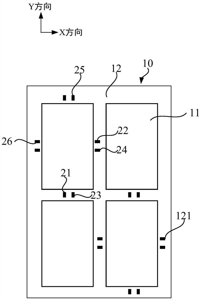
[0037] The overlay precision correction method proposed by the present invention will be further described in detail below in conjunction with the accompanying drawings and specific embodiments. Advantages and features of the present invention will be apparent from the following description and claims. It should be noted that all the drawings are in a very simplified form and use imprecise scales, and are only used to facilitate and clearly assist the purpose of illustrating the embodiments of the present invention. In addition, the structures shown in the drawings are often a part of the actual structure. In particular, each drawing needs to display different emphases, and sometimes uses different scales.

[0038] The simple model in the current prior art is a linear correction model, which usually uses six parameters: translation parameters in the X and Y directions; contraction or enlargement parameters in the X and Y directions; rotation parameters; and diagonal distortio...


PUM


Abstract

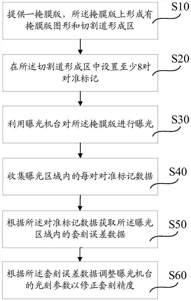
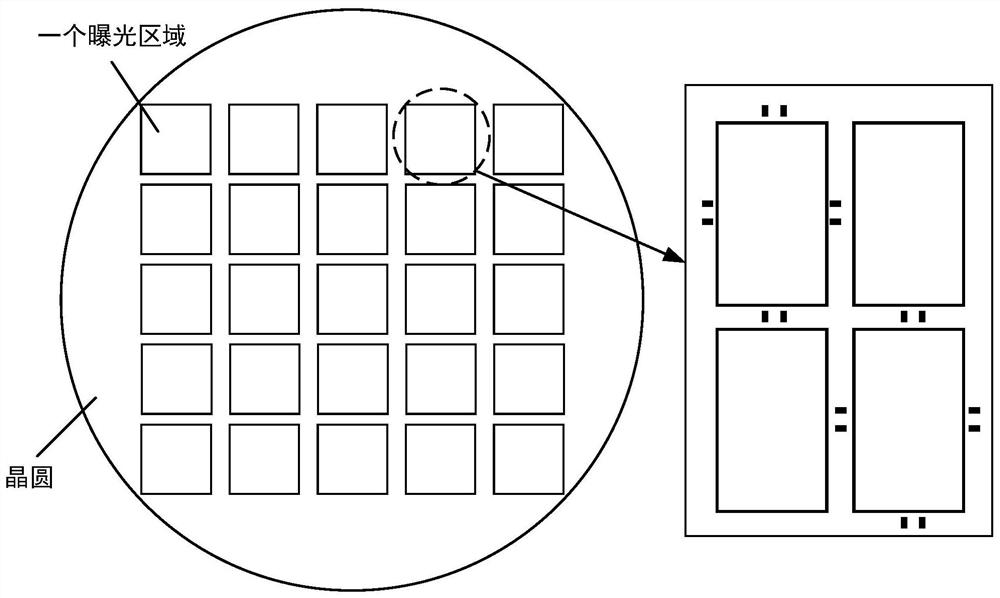
The invention provides a method for correcting overlay accuracy, comprising: providing a mask plate formed with a mask pattern and a scribe line formation area, and setting at least 8 pairs of alignment marks in the scribe line formation area; The machine exposes the mask plate; collects all alignment mark data in the exposure area; obtains overlay error data in the exposure area according to the alignment mark data; adjusts exposure according to the overlay error data The lithography parameters of the machine are used to correct the overlay accuracy. Setting at least 8 pairs of alignment marks in the scribe line formation area to obtain overlay error data in the exposure area to introduce a high-order correction amount, which can realize high-order correction inside the exposure area on the basis of linear correction, Thereby reducing the engraving error and improving the engraving accuracy.

Description

technical field [0001] The invention relates to the technical field of semiconductor manufacturing, in particular to an overlay accuracy correction method. Background technique [0002] As the size of semiconductor devices continues to shrink, devices have higher requirements for overlay alignment. In the current correction of overlay accuracy, for the dielectric layer that needs to be ion implanted or etched, in the exposure area, the mask There is only a pair of alignment marks on the plate and the medium layer. The correction obtained by the alignment marks can only be a linear correction, and the smaller units inside the exposure area cannot be corrected. The ordinary linear correction of the exposure machine cannot be very fast. Correct the error between the actual grid and the ideal grid. [0003] At present, the usual practice in this field is to rely on the results of overlay error measurement to correct the inside of the exposure area, and feed the compensation dat...

Claims


Application Information

Patent Timeline
Patent Type & Authority Patents(China)
IPC IPC(8): G03F7/20
CPCG03F7/70516G03F7/70633
Inventor 王敏王海舟
Owner SHANGHAI HUALI MICROELECTRONICS CORP
Why Eureka
Try Eureka