
Overlay error detection pattern and method

An overlay error and pattern detection technology, which is applied in the overlay error detection pattern field, can solve the problems of rising production costs, decreased device performance, and decreased production yield, so as to reduce time costs, structure regularity, and reduce overlay errors. Effect

Active Publication Date: 2021-04-06
YANGTZE MEMORY TECH CO LTD
View PDF11 Cites 0 Cited by
  • Summary
  • Abstract
  • Description
  • Claims
  • Application Information

AI Technical Summary

Problems solved by technology

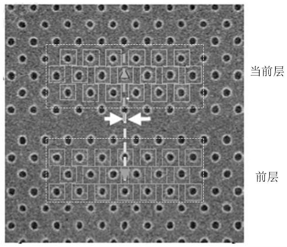
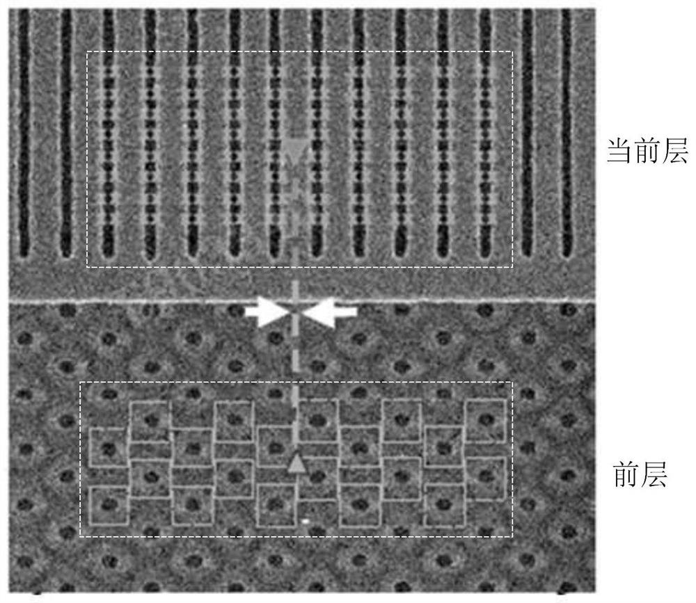
[0003] In view of the shortcomings of the prior art described above, the purpose of the present invention is to provide an overlay error detection pattern and method, which is used to solve the problem that the overlay error detection pattern used in the prior art adopts the design of an analog semiconductor device, and the design size is relatively small. Large and usually placed in the dicing line, it will be affected by the film stack and stress of the dicing line. The measurement results are likely to have a large difference from the true value of the overlay error in the die, resulting in a decrease in overlay accuracy and ultimately a decrease in device performance. Even complete failure, leading to problems such as a decline in production yield and an increase in production costs

Method used


Image

  • Overlay error detection pattern and method
  • Overlay error detection pattern and method
  • Overlay error detection pattern and method

Examples


Embodiment Construction

[0020] The implementation of the present invention will be illustrated by specific specific examples below, and those skilled in the art can easily understand other advantages and effects of the present invention from the contents disclosed in this specification.

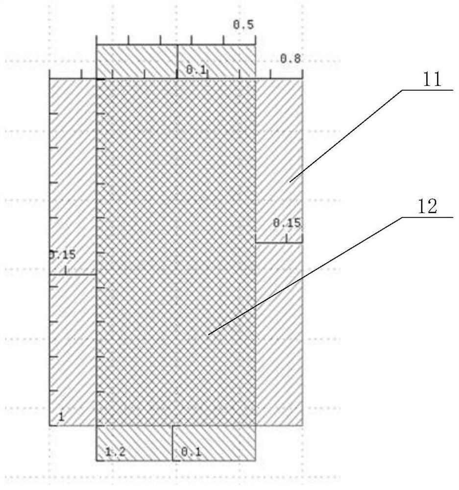
[0021] see Figure 3 to Figure 6 . It should be noted that the structures, proportions, sizes, etc. shown in the drawings attached to this specification are only used to match the content disclosed in the specification, for those who are familiar with this technology to understand and read, and are not used to limit the implementation of the present invention. Limiting conditions, so there is no technical substantive meaning, any modification of structure, change of proportional relationship or adjustment of size, without affecting the effect and purpose of the present invention, should still fall within the scope of the present invention. within the scope covered by the disclosed technical content. At the same ti...


PUM


Abstract

The invention provides an overlay error detection pattern and method. The pattern comprises a first pattern and a second pattern which are formed on the two film layers stacked up and down, wherein the first pattern and the second pattern are correspondingly arranged up and down, and center points are located on the same vertical line; the first pattern comprises a single first rectangular pattern, the second pattern comprises one or more second rectangular patterns, the ratio of the long sides to the short sides of the first rectangular pattern is smaller than that of the long sides to the short sides of the second rectangular pattern, and the orthographic projection of the middle part of the second rectangular pattern in the direction perpendicular to the first rectangular pattern falls into the first rectangular pattern; orthographic projections of the two ends connected with the middle part are located outside the first rectangular graph. According to the pattern, the planar area occupied by the pattern can be reduced on the premise of realizing the measurement purpose, so that the pattern can be distributed in the crystal grain, the cutting channel film stack is closer to a device in the crystal grain, the overlay error can be effectively reduced, the production yield is improved, and production cost is reduced.

Description

technical field [0001] The invention relates to the technical field of semiconductor manufacturing, in particular to a photolithography process, in particular to an overlay error detection pattern and method. Background technique [0002] Photolithography is a very important process in the semiconductor chip manufacturing process. It uses a technology similar to photo printing to print the fine patterns on the mask plate onto the wafer through light exposure. With the rapid development of semiconductor manufacturing technology and the increasing functions of consumer electronics products, the integration of devices is getting higher and higher, and the feature size of semiconductor devices is constantly shrinking, which puts forward higher and higher requirements for photolithography. A very important task in the photolithography process is to perform interlayer alignment, that is, overlay alignment (overlay), so as to ensure the difference between the current pattern (ie, t...

Claims


Application Information

Patent Timeline
Patent Type & Authority Applications(China)
IPC IPC(8): G03F7/20
CPCG03F7/70633
Inventor 陈媛邱瑾玉耿玉慧宋之洋
Owner YANGTZE MEMORY TECH CO LTD
Learn More