Relay Coil Drive Circuit

a technology of relay coil and drive circuit, which is applied in the direction of relays, electromagnetic relays, electrical apparatus, etc., can solve the problems of wasting more power than the contactor itself, requiring a significant amount of power to operate, and the transformer can be larger, so as to reduce the prolonged low pressure

Inactive Publication Date: 2010-10-21
MECHANICAL INGENUITY CORP
View PDF2 Cites 38 Cited by
  • Summary
  • Abstract
  • Description
  • Claims
  • Application Information

AI Technical Summary

Benefits of technology

[0021]Relay contacts operate with a snap action when disclosed electronic waveforms, profile its coil current. Snap action reduces the prolonged low pressure that damages relay contacts. This means of driving the relay coil also reverses the properties of its voltage and current. Coil voltage now varies with movement of its armature, frame current, coil resistance, back-EMF, and temperature. Coil current follows a profile that is stable and independent of these changing electrical, mechanical, and environmental factors. Since coil voltage has no direct magnetic or mechanical effect its changes do not affect relay operation. However the relays new stable current profile has a dramatic affect. It moves, makes, breaks and seats predictably, regardless of its temperature, residual magnetism, or mechanical wear. Power-line synchronization means takes advantage of this new stability, concentrating on the pos

Problems solved by technology

The undesirable aspects of the contactor are that it is large and heavy, and all this hammering requires a significant amount of power to operate.
Customarily they use a safer coil voltage, usually 24-volts AC, and the resulting transformer can be larger, heavier and waste more power than the contactor itself.
When a contactor operates it makes a loud noise and it also has a limited life, typically around 100,000-cycles on motor loads.
Efficiency is the issue of this millennium such that a lot more effort and cost is going into reducing wasted energy.
At 40-amps, solid state relays waste 60-watts, due to their inherent voltage drop and cooling fans add to these losses.
A savings in energy is historically accompanied by an increase in cost.
However, the problems associated with using PC-relays to control motor loads are considerable and for the most part hidden.
Failures occur in situations far below their ratings, defying conventional wisdom.
Some of these problems may be rationalized since they lack the hammer action and raw power of the industrial contactor.
But pc-relays also seem to be less reliable than ordinary switches such as wall switches, limit switches, or even temperature switches.
Dynamically (in-motion) several major problems develop.
Unfortunately until the armature seats (18) bending leaf spring (20), pressure between the contacts is low.
This long delay in developing contact pressure is problematic.
With light contact pressure the relay cannot handle its rated current and certainly cannot handle inrush currents.
Bounce in a signal wire is awkward, but with a high current load, it is a disaster.
These naturally occurring electromechanical properties are just not good for closing electrical contacts.
Making dynamic coil current unusually hard to control.
A closing armatures positive dL/dt voltage unbalances the equation, forcing di/dt to respond by going negative, lowering instantaneous current.
Making coil resistance hard to predict.
Opening relay contacts produces problems similar to those encountered when closing

Method used


Image

  • Relay Coil Drive Circuit
  • Relay Coil Drive Circuit
  • Relay Coil Drive Circuit

Examples


Embodiment Construction

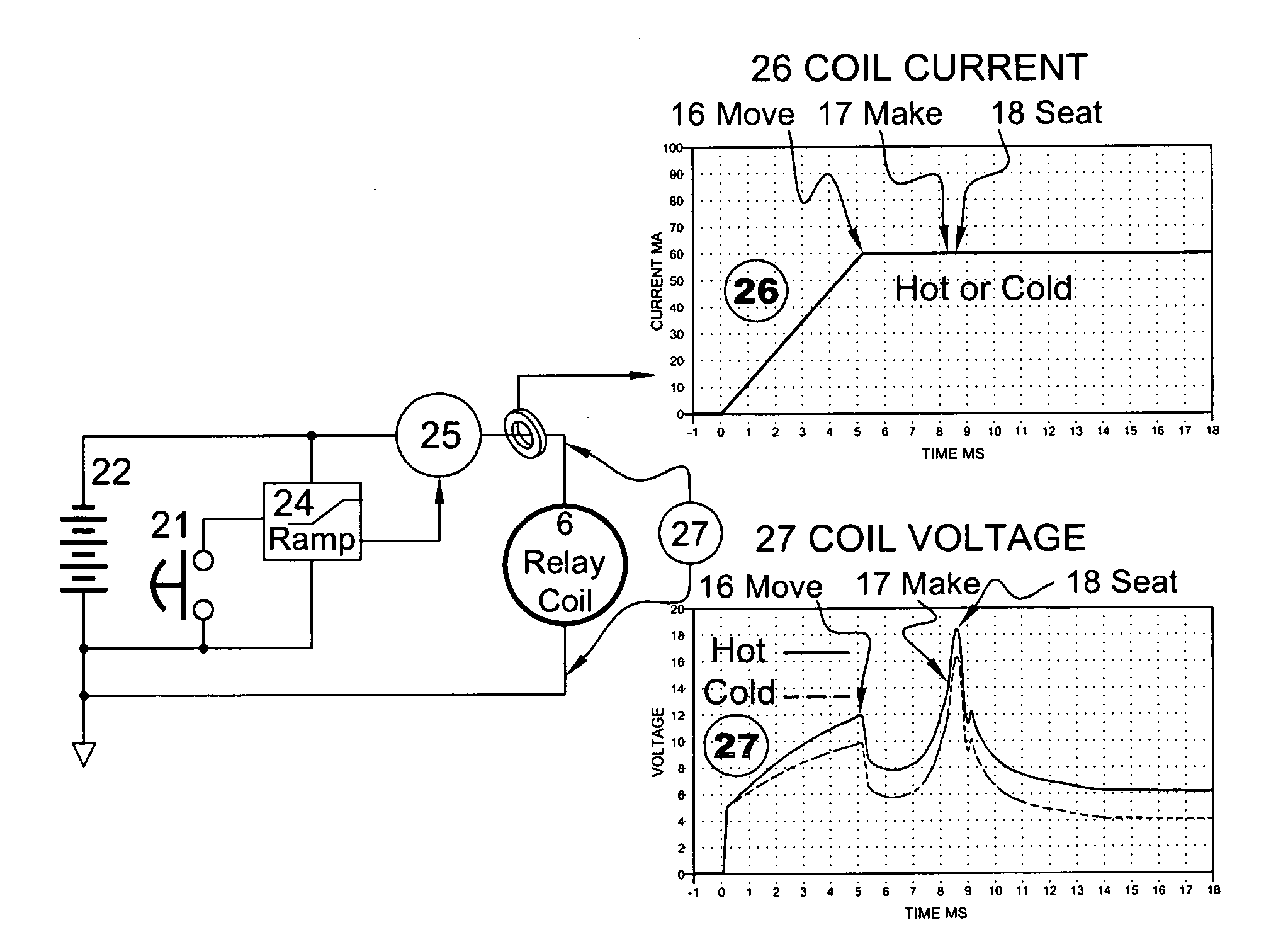
[0029]Wrestling current control away from the PC-relay coil solves much of its operational problems and tightly controls its timing. This is made difficult by the relays tendency to control its own current. A simple current / voltage source switched into the coil at time zero cannot produce current for a long time. Defeated by the relay coil's infinitely efficient (di / dt) rebalancing of the equation. Such rebalancing will include (iR) temperature problems and (dL / dt) armature movement problems. The inventive means therefore controls both (di / dt) and (i). Since it is impossible to solve the relays operational problems after it finishes operating, the invention regulates (di / dt) and (i) beginning at time zero.

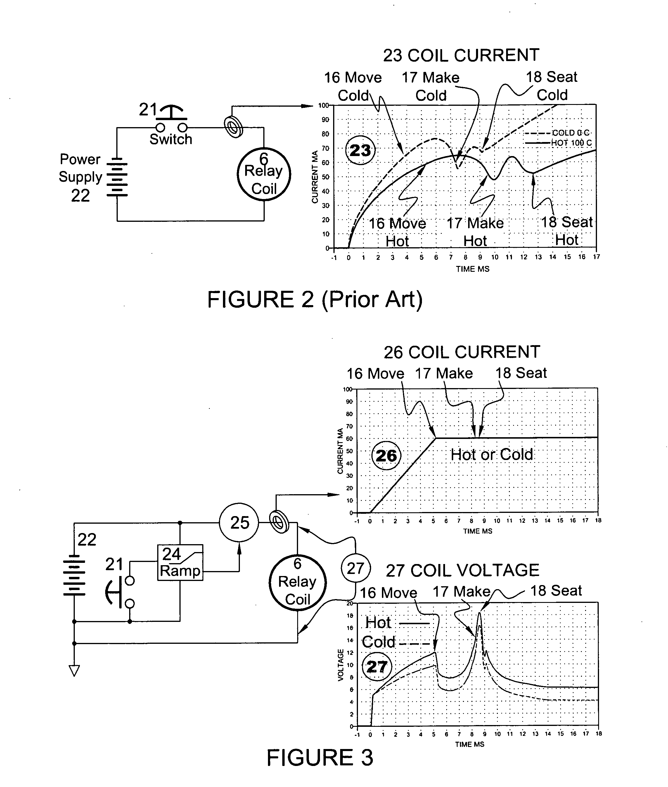
[0030]FIG. 3 illustrates the inventive system; Pressing switch (21) at time zero starts ramp (24) which profiles the current coming from the output of an externally controlled current source (25). The preferred embodiment's have a current controlled current source (current mirror) ...


PUM


Abstract

Relay contacts operate with a snap action when disclosed electronic waveforms, profile its coil current. Snap action reduces the prolonged low pressure that damages relay contacts. This means of driving the relay coil also reverses the properties of its voltage and current. Coil voltage now varies with movement of its armature, frame current, coil resistance, back-EMF, and temperature. Coil current follows a profile that is stable and independent of these changing electrical, mechanical, and environmental factors. Since coil voltage has no direct magnetic or mechanical effect its changes do not affect relay operation. However the relays new stable current profile has a dramatic affect. It moves, makes, breaks and seats predictably, regardless of its temperature, residual magnetism, or mechanical wear. Power-line synchronization means takes advantage of this new stability, concentrating on the position and pressure of the contact. The contact starts to move closed after the peak power-line voltage and makes at zero voltage. Full contact pressure is maintained until load-current is near zero and contact break occurs before zero current. Several types of coil current profiles are disclosed along with analog and software controlled embodiments. New relay friendly electronic reset logic is disclosed to maintain contact pressure during power losses caused by load-surge and load-shorts. Zero crossing and power-line voltage are combined with logic that does not disable but delays relay operation. Relay contact to coil noise problems are disclosed along with suppression techniques to stop electronic circuitry induced contact chatter. Diagnostic techniques and production methods are disclosed for relays that are sealed inside an enclosure. Automatic and manual timing adjustment means are also disclosed.

Description

BACKGROUND OF THE INVENTION[0001]The technical field of this invention relates to a method of using pc-relays to run loads normally reserved for larger industrial contactors. An industrial contactor is not just a bigger relay; at its heart is a powerful solenoid with an ability to deliver lots of force. It hammers contacts together to make an electrical connection and then hammers apart the contacts breaking that connection. Worn, pitted, or dirty contacts make a solid electrical connection because mashing the conductors together forces irregular surfaces to mate. Remove coil power from the contactor and a set of stiff springs accelerate its massive armature into the made contacts, breaking apart contact welds. Years of experience proves this method of operation to be very reliable. In the home, contactors operate air conditioners, pumps and other motor loads. In industry they are used to control nearly every load. As a result there are hundreds of millions in operation and millions...

Claims


Application Information

Patent Timeline
IPC IPC(8): H01H47/22
CPCH01H47/22
Inventor BECKERMAN, HOWARD
Owner MECHANICAL INGENUITY CORP
Why Eureka
Try Eureka