Ultra-thin heat pipe

a heat pipe and ultra-thin technology, applied in the direction of indirect heat exchangers, cores/yokes, light and heating apparatus, etc., can solve the problems of heat transfer through the interface between the insert and the metal tube, and achieve the effect of compressing sufficiently and reducing the thermal contact resistan

Inactive Publication Date: 2010-10-21
YEH CHIANG TECH CORP
View PDF8 Cites 37 Cited by
  • Summary
  • Abstract
  • Description
  • Claims
  • Application Information

AI Technical Summary

Benefits of technology

[0008]Another object of the present invention is to provide an ultra-thin heat pipe which can be compressed sufficiently without damaging the wick structure.
[0009]Still another object of the present invention is to provide an ultra-thin heat pipe which can reduce the thermal contact resistance between the wick structure and the metal tube.

Problems solved by technology

This disadvantageous to heat transfer through the interface between the insert and the metal tube.

Method used


Image

  • Ultra-thin heat pipe
  • Ultra-thin heat pipe
  • Ultra-thin heat pipe

Examples


Embodiment Construction

[0015]Now, the preferred embodiments according to the present invention will be described in conjunction with the accompanying drawings. For the sake of convenience, the drawings are not made to scale.

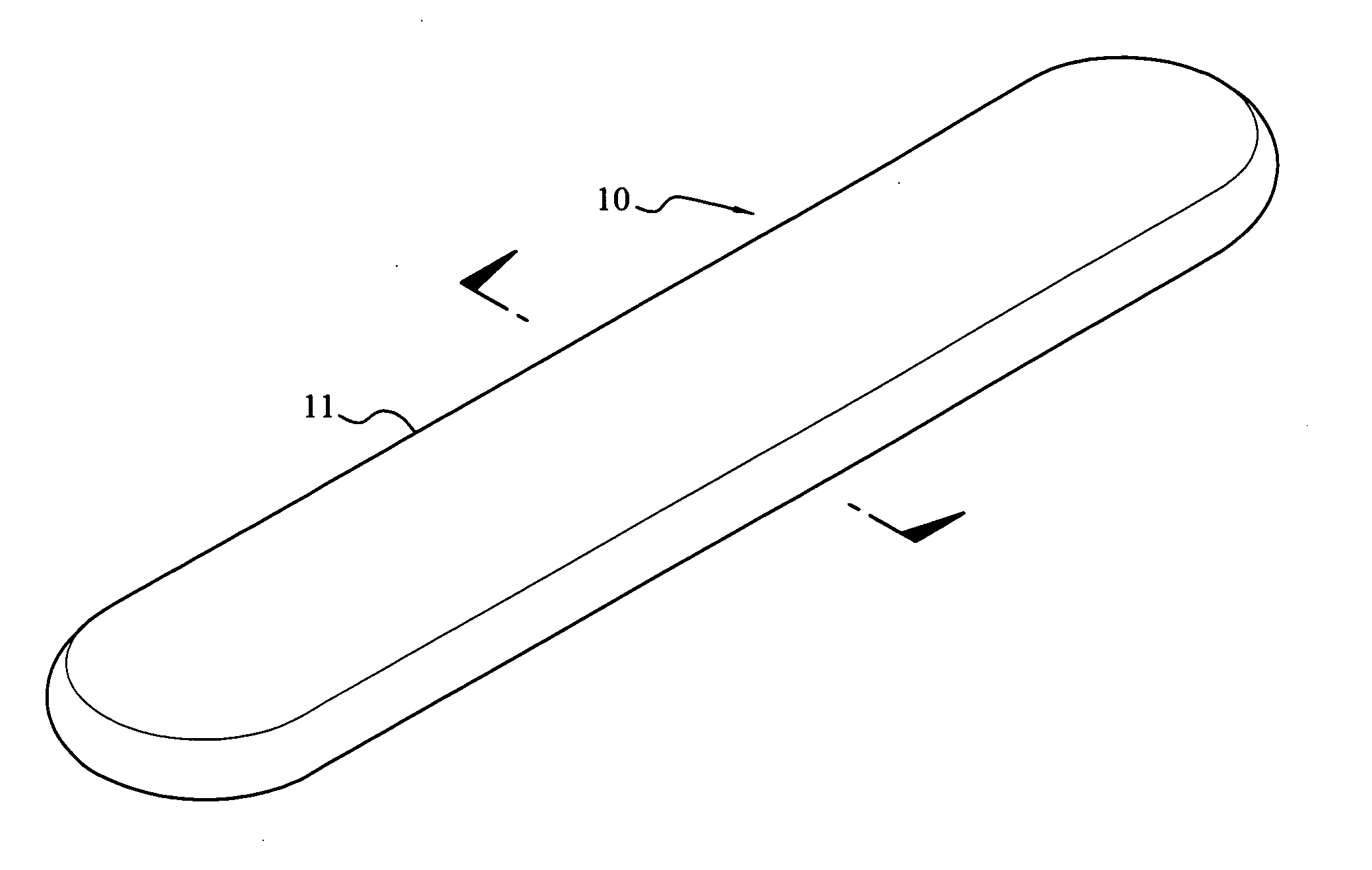
[0016]FIG. 1 is a perspective view showing the ultra-thin heat pipe according to the present invention which is indicated by reference 10.

[0017]The heat pipe 10 comprises a hollow metal tube 11 and a sintered powder portion formed on the inner face of the metal tube 11. The metal tube 11 is made, for example, from Cu, Al, stainless steel, Ti or Ni. The sintered powder portion is formed by sintering Cu powder, Al powder, Ni powder or nano carbon powder. A plurality of capillary grooves extending axially (not shown) may be formed on the inner wall face of the metal tube 11.

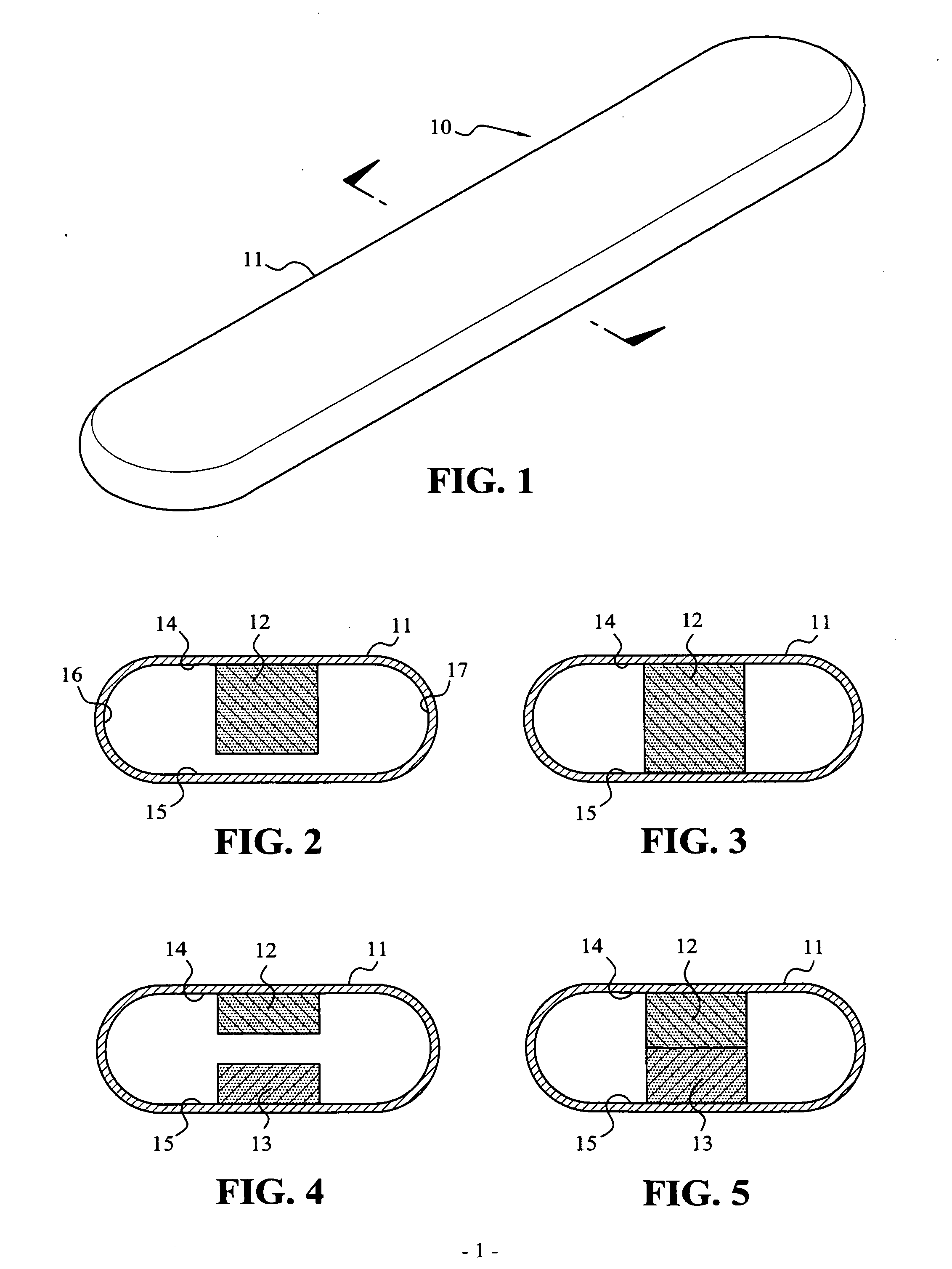
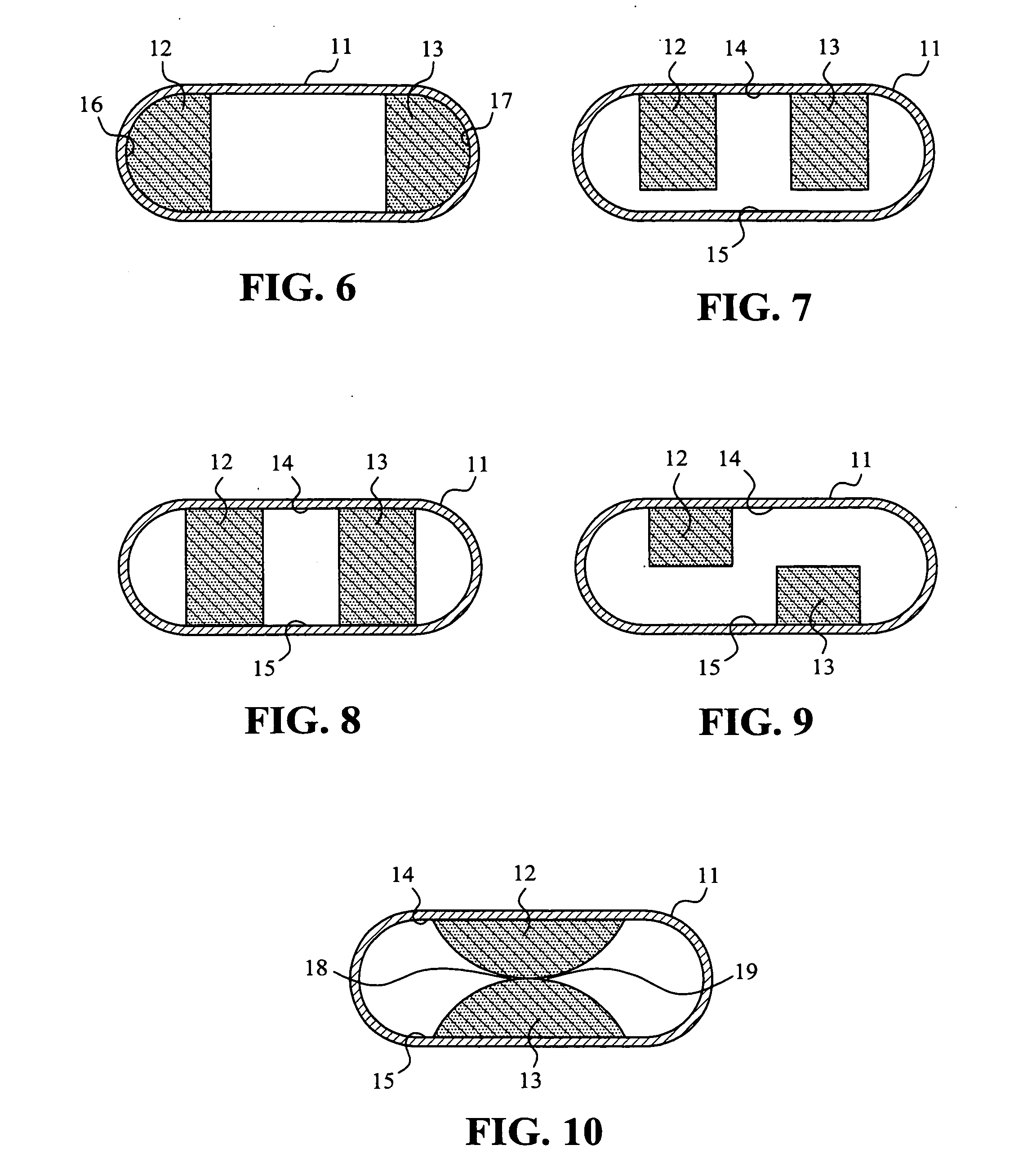
[0018]FIGS. 2 to 10 are cross sections perpendicular to the axial direction of the metal tube 11, which show various arrangements of the sintered powder portion.

[0019]The metal tube 11 includes an upper tube wall 14, a...


PUM

PropertyMeasurementUnit
included angleaaaaaaaaaa
heat transfer capabilityaaaaaaaaaa
speedaaaaaaaaaa

Abstract

An ultra-thin heat pipe comprises a flat metal tube and one or more sintered powder portions. The flat metal tube has an upper tube wall, a lower tube wall and two lateral walls connecting with the upper tube wall and the lower tube wall. The sintered powder portions extends axially and are formed on an inner face of at least one of the upper tube wall, the lower tube wall and the lateral walls such that vapor passage space is formed at one or more sides of the sintered powder portions.

Description

BACKGROUND OF THE INVENTION[0001]1. Field of the Invention[0002]The present invention relates to an ultra-thin heat pipe, especially to a sintered ultra-thin heat pipe.[0003]2. Brief Description of the Prior Art[0004]It is known that a heat pipe is a device having high heat transfer capability. The liquid working medium filled in the heat pipe is evaporated at the hot segment into vapor. The vapor moves at a high speed along the vapor passage toward the cold segment. Then, the vapor is condensed into liquid working medium at the cold segment, and the liquid working medium, under the capillary action, returns to the hot segment through the wick structure. In this manner, heat can be transferred promptly from the hot segment to the cold segment.[0005]Accompanying with the trend of miniaturization and flattening of electronic products, there is a demand for a flat heat pipe. U.S. Patent Publication No. 2002179288A1 proposes to insert a pre-fabricated pipe wick in a tubular copper tube ...

Claims


Application Information

Patent Timeline
Patent Type & Authority Applications(United States)
IPC IPC(8): B32B15/16B32B15/01
CPCB22F7/08B32B15/01F28D15/0233Y10T428/1209F28F2255/18Y10T428/12063F28D15/046
Inventor LEE, KE-CHIN
Owner YEH CHIANG TECH CORP
Why Eureka
Try Eureka