Battery module and battery pack using said battery module
a battery module and battery pack technology, applied in the field of batteries, can solve the problems of not knowing how to suppress the influence cannot prevent the deterioration cannot disclose the effect of one battery failure on the surrounding battery, so as to prevent abnormal overheating of the surrounding battery, prevent fire from spreading, and excellent reliability
- Summary
- Abstract
- Description
- Claims
- Application Information
AI Technical Summary
Benefits of technology
Problems solved by technology
Method used
Image

Examples
first exemplary embodiment
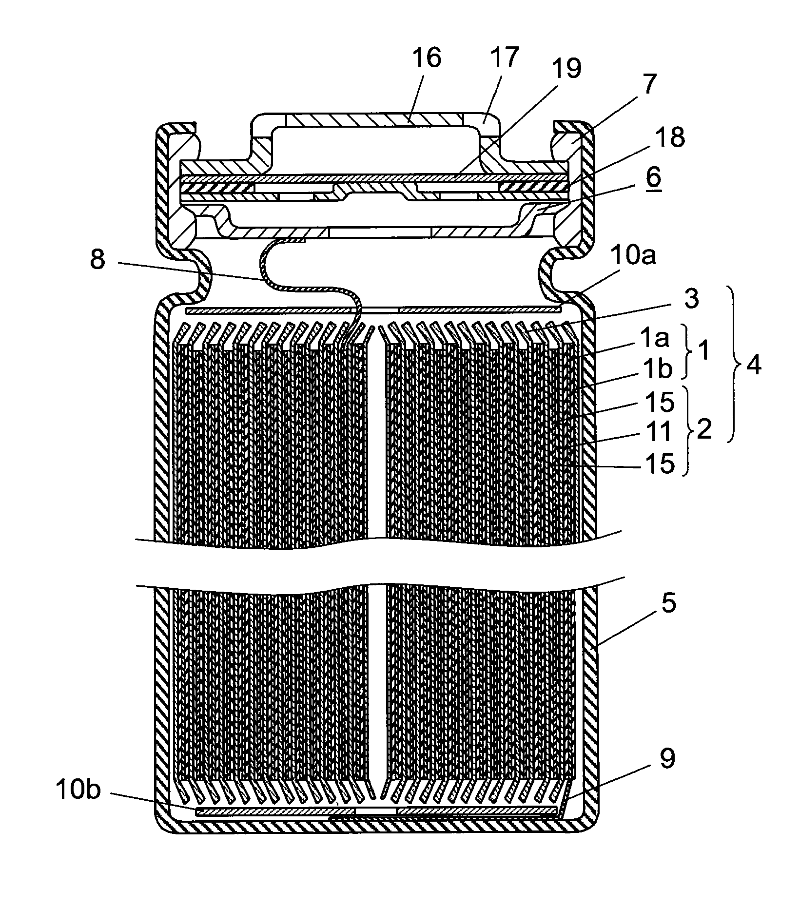
[0074]FIG. 1 is a cross-sectional view showing a battery accommodated in a battery module in accordance with a first exemplary embodiment of the present invention.
[0075]As shown in FIG. 1, a cylindrical battery has electrode group 4 in which positive electrode 1 provided with positive electrode lead 8 made of, for example, aluminum and negative electrode 2 facing positive electrode 1 and provided with positive electrode lead 9 made of, for example, copper at one end are wound together with separator 3 interposed therebetween. Then, insulating plates 10a and 10b are mounted on the upper and lower parts of electrode group 4, which are inserted into battery case 5. The other end of positive electrode lead 8 is welded on sealing plate 6 and the other end of negative electrode lead 9 is welded on the bottom of battery case 5. Furthermore, a non-aqueous electrolyte (not shown) conducting lithium ion is injected into battery case 5. Then, an open end of battery case 5 is caulked with respe...
second exemplary embodiment
[0094]Hereinafter, a battery module in accordance with a second exemplary embodiment of the present invention is described in detail with reference to FIGS. 4A and 4B.
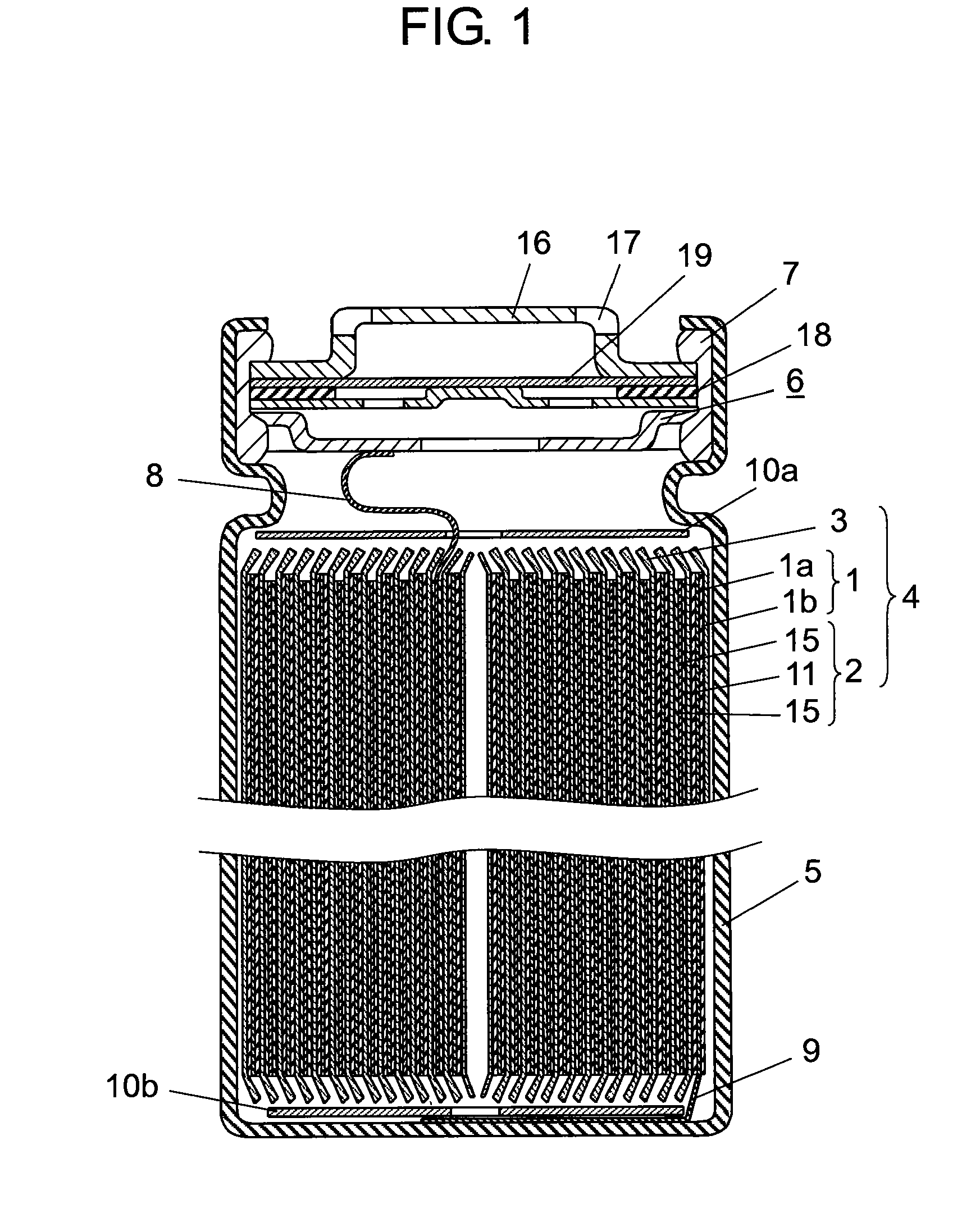
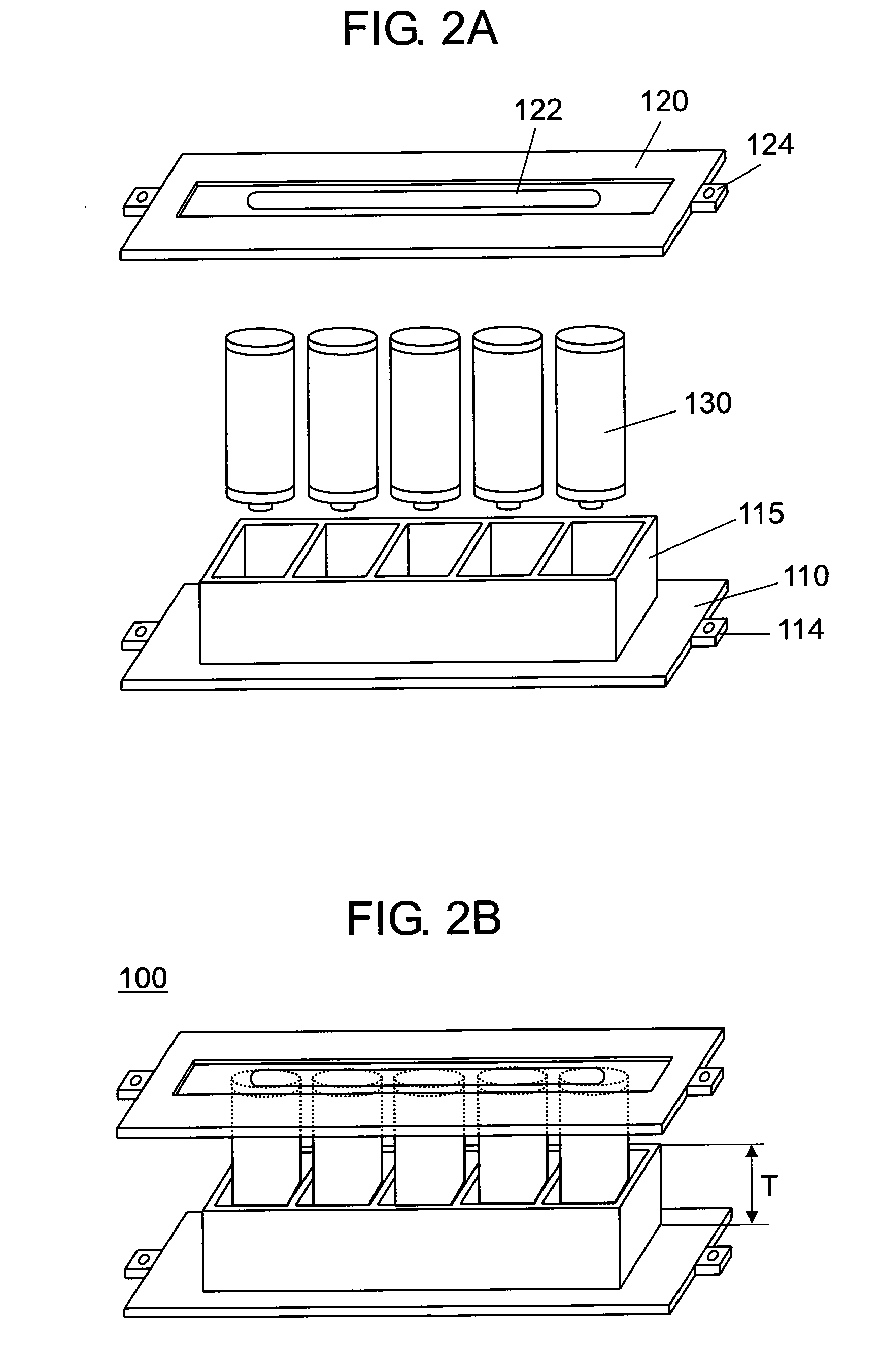
[0095]FIG. 4A is an exploded perspective view of a battery module in accordance with a second exemplary embodiment of the present invention. FIG. 4B is a perspective view of the battery module in accordance with the second exemplary embodiment of the present invention.
[0096]As shown in FIG. 4A, in battery module 300, first enclosure 310 is provided with first partition member 315 and second enclosure 320 is provided with second partition member 325 corresponding to each of a plurality of batteries 330 to be accommodated. This exemplary embodiment is different from the first exemplary embodiment in that air holes 350 are provided on the outer wall of any one of first partition member 315 and second partition member 325 in vicinity of the vent holes of batteries 330. Furthermore, the total of height T1 (depth) of first p...
third exemplary embodiment
[0102]Hereinafter, a battery module in accordance with a third exemplary embodiment of the present invention is described in detail with reference to FIGS. 6A and 6B.
[0103]FIG. 6A is an exploded perspective view of a battery module in accordance with the third exemplary embodiment of the present invention. FIG. 6B is a perspective view of the battery module in accordance with the third exemplary embodiment of the present invention.
[0104]As shown in FIG. 6B, the battery module of this exemplary embodiment is different from the battery module in the second exemplary embodiment in that the total of height T3 (depth) of first partition member 515 and height T4 (depth) of second partition member 525 is made to be smaller than the height of the batteries and the difference (gap) between the total and the height of the battery is used as an air hole.
[0105]That is to say, as shown in FIG. 6A, battery module 500 has a configuration in which first enclosure 510 is provided with first partitio...
PUM
 Abstract
Description
Claims
Application Information
 - R&D
- Intellectual Property
- Life Sciences
- Materials
- Tech Scout
- Unparalleled Data Quality
- Higher Quality Content
- 60% Fewer Hallucinations
Browse by: Latest US Patents, China's latest patents, Technical Efficacy Thesaurus, Application Domain, Technology Topic, Popular Technical Reports.
© 2025 PatSnap. All rights reserved.Legal|Privacy policy|Modern Slavery Act Transparency Statement|Sitemap|About US| Contact US: help@patsnap.com