Air conditioning apparatus

a technology for air conditioning apparatus and fan motor, which is applied in the direction of lighting and heating apparatus, heating types, liquid fuel engines, etc., can solve the problems of affecting the efficiency of air conditioning equipment, so as to prevent abnormal overheating of the fan motor and prevent the effect of fan motor heating

Active Publication Date: 2015-10-22
DAIKIN IND LTD
View PDF12 Cites 0 Cited by
  • Summary
  • Abstract
  • Description
  • Claims
  • Application Information

AI Technical Summary

Benefits of technology

[0027]As described above, when the fan motor is herein disposed in the fan downwind space, the motor heat shield member is designed to be further provided. With the construction, it is possible to prevent heating of the fan motor by radiant heat from the heating means.
[0028]Consequently, it is herein possible to prevent abnormal overheating of the fan motor by radiant heat from the heating means.

Problems solved by technology

However, when an event occurs that an operation of the centrifugal fan stops due to a trouble of a fan motor or so firth while an operation of the heating means continues, a bladed wheel of the centrifugal fan is inevitably heated by radiant heat from the heating means.
At this time, when a bladed wheel made of resin is employed as the bladed wheel for the centrifugal fan, chances are that the resin bladed wheel is damaged or broken by the radiant heat from the heating means.
Therefore, it is difficult to employ such a resin bladed wheel as a bladed wheel for a rearward bladed centrifugal fan when heating means is mounted in the vicinity of a blow-out port in an air conditioning apparatus that the rearward bladed centrifugal fan is mounted in a fan compartment having a fan entrance bored in opposition to the blow-out port such that a rotary shaft of the centrifugal fan is oriented to an opening direction of the fan entrance and an opening direction of the blow-out port.
With the construction, it can be herein made difficult to transfer radiant heat from the heating means to the hub through the fan heat shield member.

Method used


Image

  • Air conditioning apparatus
  • Air conditioning apparatus
  • Air conditioning apparatus

Examples


Embodiment Construction

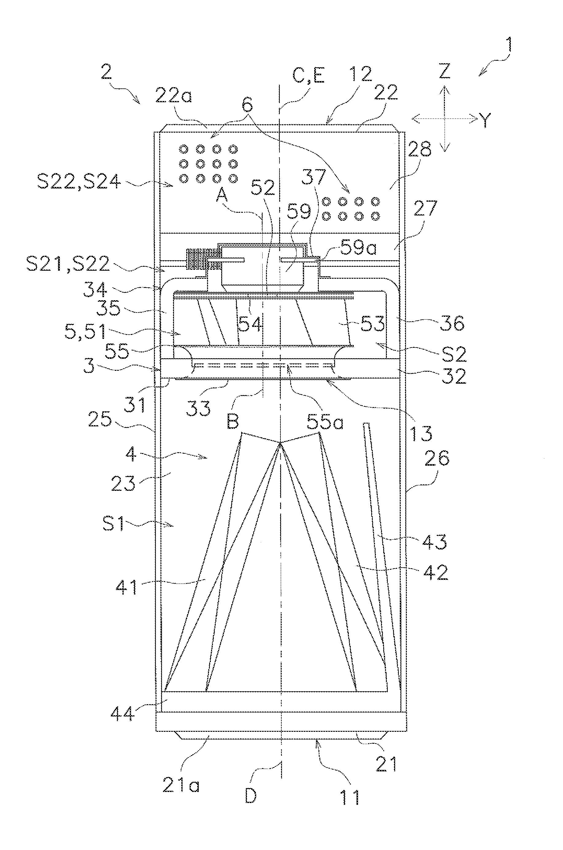
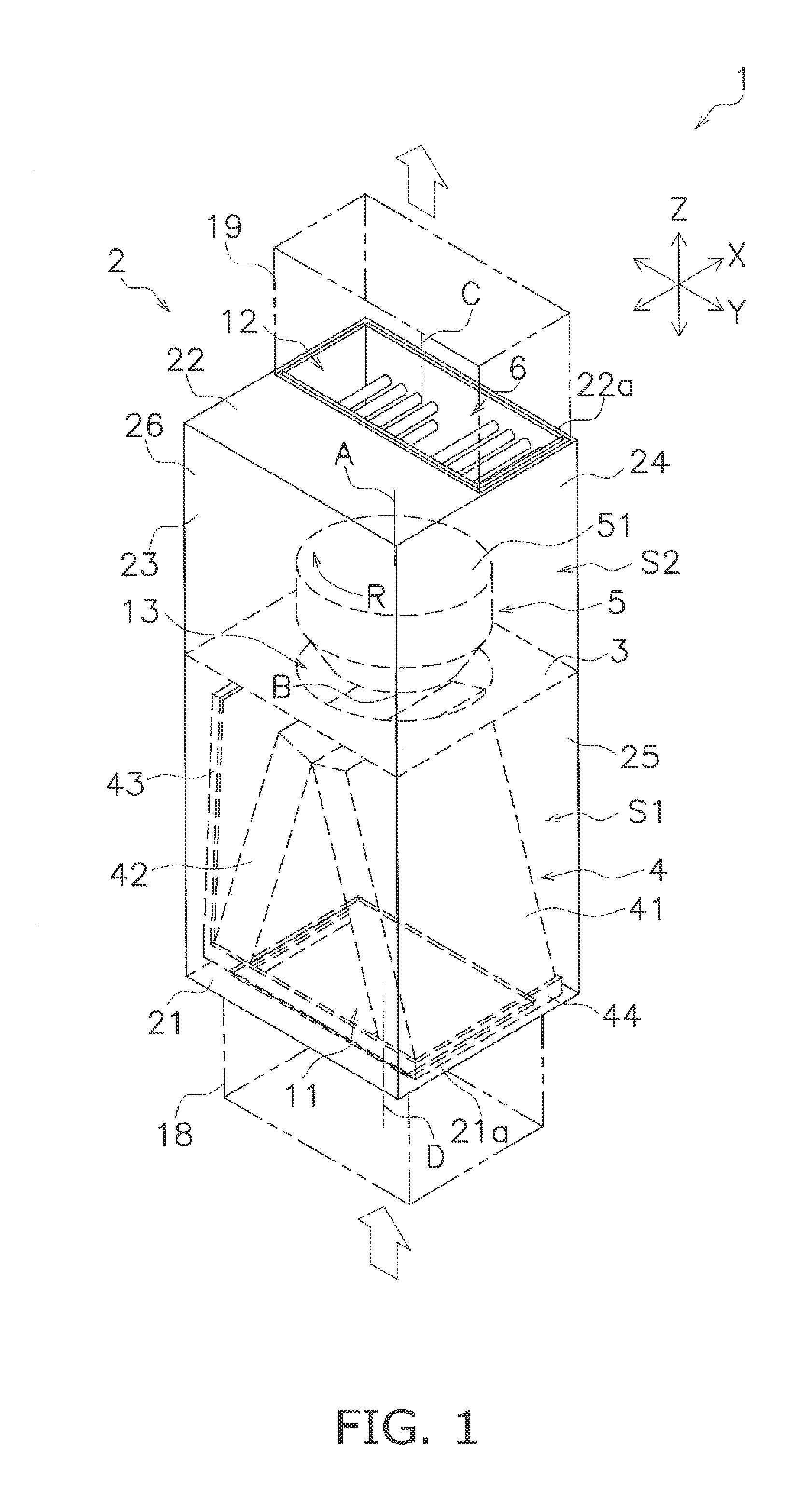
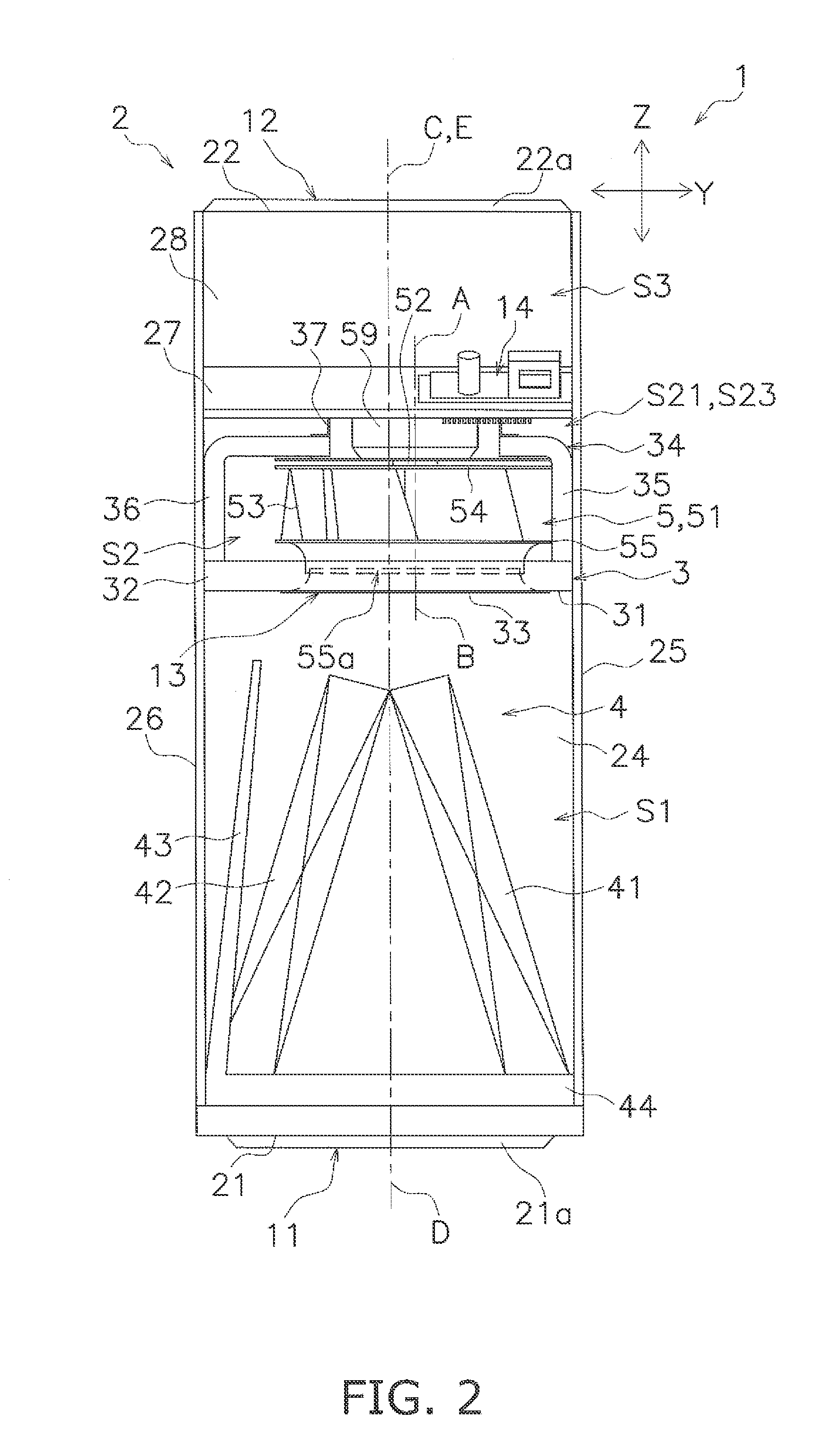
[0047]An air conditioning apparatus according to a preferred embodiment of the present invention will be hereinafter explained on the basis of the attached drawings. It should be noted that a specific construction of the air conditioning apparatus according to the present invention is not limited to the following preferred embodiment and the modifications thereof, and can be changed without departing from the scope of the present invention.

[0048](1) Basic Construction of Air Conditioning Apparatus

[0049]First, a basic construction of an air conditioning apparatus 1 will be explained with FIGS. 1 to 8. Here, FIG. 1 is an external perspective view of the air conditioning apparatus 1 according to the preferred embodiment of the present invention (in a vertical mount configuration). FIG. 2 is a front lateral view of the air conditioning apparatus 1 from which a first lateral part 23 is detached (in the vertical mount configuration). FIG. 3 is a rear lateral view of the air conditioning a...


PUM

PropertyMeasurementUnit
sizeaaaaaaaaaa
outer diameteraaaaaaaaaa
dimensionaaaaaaaaaa

Abstract

An air conditioning apparatus includes a casing having intake and blow-out ports, a partition member dividing an interior of the casing, a heat exchanger, a centrifugal fan, a heater and a fan heat shield. The centrifugal fan includes a bladed wheel mounted in the fan compartment such that a rotary shaft of the bladed wheel is oriented along an opening direction of the fan entrance and an opening direction of the blow-out port, and the bladed wheel being made of resin. The heater is mounted in a blow-out port opposed space opposed to the blow-out port within a fan downwind space located on a downwind side of the bladed wheel within the fan compartment. The fan heat shield member is mounted in the fan downwind space in order to cover a part of the bladed wheel that is opposed to the heater.

Description

CROSS-REFERENCE TO RELATED APPLICATIONS[0001]This application claims priority under 35 U.S.C. §119 to Japanese Patent Application No. 2014-086209, filed Apr. 18, 2014. The entire disclosure of Japanese Patent Application No. 2014-086209 is hereby incorporated herein by reference.FIELD OF THE INVENTION[0002]The present invention relates to an air conditioning apparatus, particularly to an air conditioning apparatus that a rearward bladed centrifugal fan is mounted in a fan compartment having a fan entrance bored in opposition to a blow-out port such that a rotary shaft of the centrifugal fan is oriented to an opening direction of the fan entrance and an opening direction of the blow-out port.BACKGROUND INFORMATION[0003]As described in Japan Laid-open Patent Application Publication No. H06-281194, an air conditioning apparatus has been produced so far that a rearward bladed centrifugal fan is mounted in a ventilation unit (a fan compartment) having a fan entrance bored in opposition t...

Claims


Application Information

Patent Timeline
Patent Type & Authority Applications(United States)
IPC IPC(8): F04D17/08F04D29/40
CPCF04D29/403F04D17/08F24F1/0022F04D29/023F04D29/281F04D29/5853F05D2300/44
Inventor YOKOYAMA, NAOFUMIYOKOMIZO, TSUYOSHIYAMASAKI, TAKAHIROKASHIHARA, TAKASHIMORI, AKIHIKO
Owner DAIKIN IND LTD
Why Eureka
Try Eureka