Medical Instrument, In Particular Hysteroscope

a technology of hysteroscope and medical instrument, which is applied in the field of instruments, can solve the problems of pain for patients, not only uncomfortable for patients, but also very painful

Active Publication Date: 2010-10-21
KARL STORZ GMBH & CO KG
View PDF29 Cites 9 Cited by
  • Summary
  • Abstract
  • Description
  • Claims
  • Application Information

AI Technical Summary

Benefits of technology

[0031]This has the significant advantage in terms of handling that the operator, if for example only an examination is intended to be carried out, latches the two components to one another in that position, namely in the first position, in which the second shaft of the optical system extends beyond the first shaft of t

Problems solved by technology

This is very painful for the patient, particularly if she has diseases in the region

Method used


Image

  • Medical Instrument, In Particular Hysteroscope
  • Medical Instrument, In Particular Hysteroscope
  • Medical Instrument, In Particular Hysteroscope

Examples


Embodiment Construction

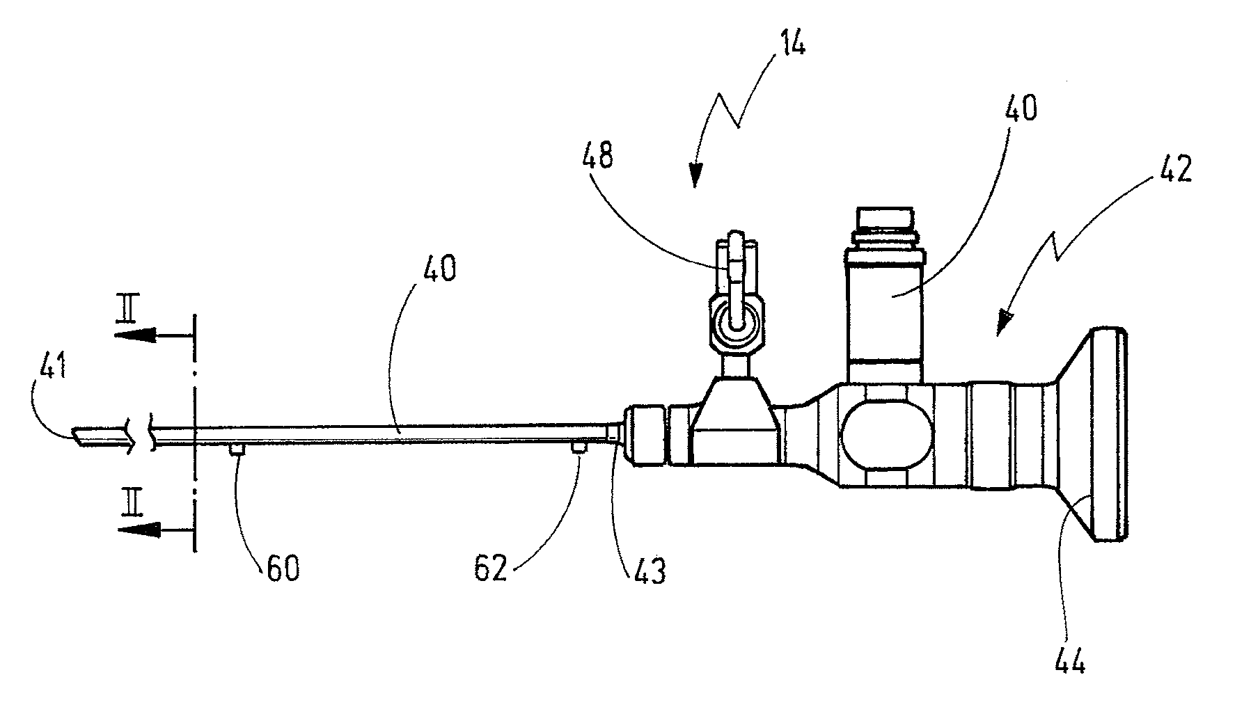
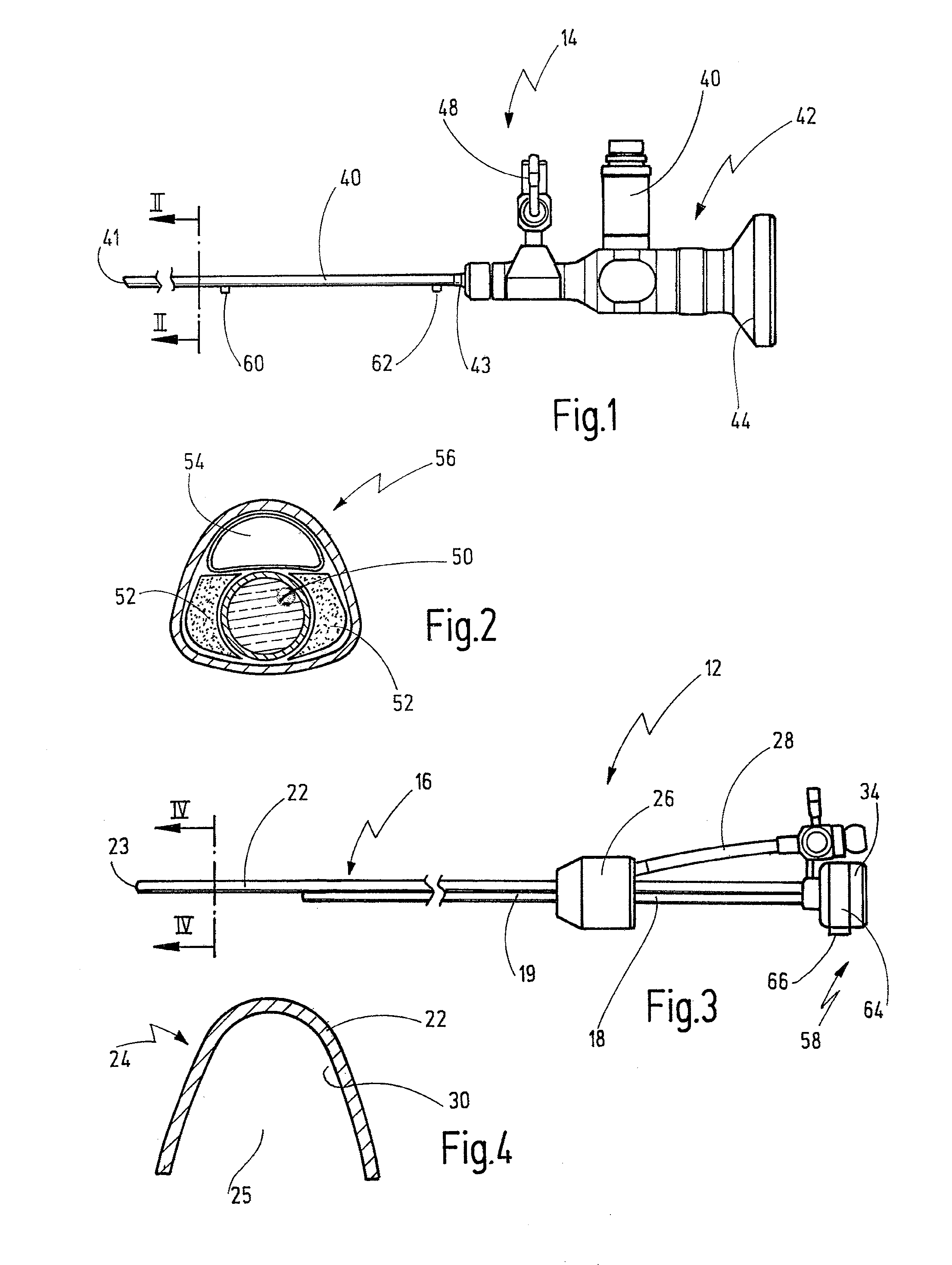
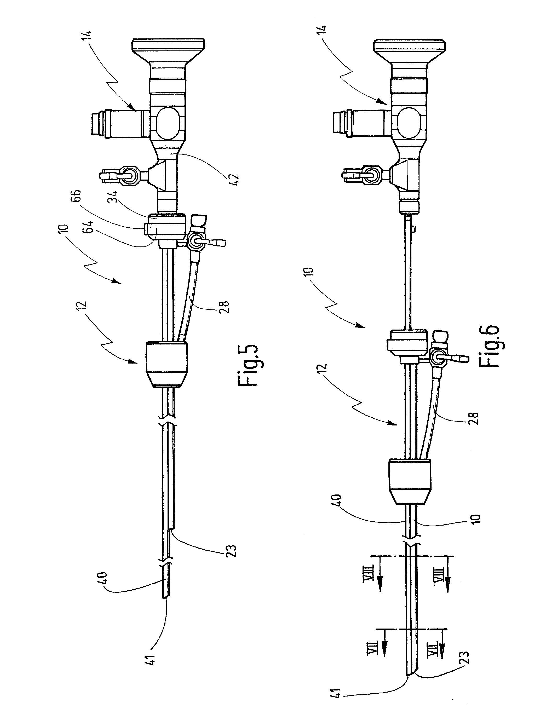
[0043]A medical instrument according to the invention, in particular a hysteroscope, illustrated in FIGS. 1 to 8, in particular in FIGS. 5 and 6, is designated in its entirety by the reference sign 10.

[0044]The instrument 10, as illustrated in FIGS. 5 and 6, consists of a shaft part 12 illustrated in FIG. 3 and an optical system 14 illustrated in FIG. 1.

[0045]The shaft part 12 illustrated in FIG. 3 has a first shaft 16, which has a proximal shaft section 18. The proximal shaft section 18 is a closed shaft and has, as can be seen from the sectional illustration in FIG. 8, an approximately oval cross section 20.

[0046]On the distal side, the first shaft 16 has a distal shaft section 22, the cross section 24 of which can be seen in FIG. 4. There it can be seen that the cross section 24 of the distal shaft section 22 is approximately U-shaped and open on one side 25.

[0047]The distal shaft section 22 ends at a rounded distal end 23.

[0048]The first shaft 16 has a housing 26 from which a co...


PUM


Abstract

A medical instrument, in particular a hysteroscope, has a shaft part (12) having a first shaft and an optical system having a second shaft (40), in which the shaft part (12) and optical system can be displaced with respect to one another along the shafts thereof such that, in a first position, the second shaft (40) of the optical system extends beyond the first shaft of the shaft part (12) on the distal side and that, in a second position, a distal end (23) of the first shaft of the shaft part (12) comes to rest approximately level with a distal end (41) of the second shaft (40) of the optical system.

Description

BACKGROUND OF THE INVENTION[0001]The invention relates to an instrument, in particular a hysteroscope.[0002]Hysteroscopes are used for inspecting the uterine cavity or for inserting instruments into the uterus through an endoscope, for example for partial resection of submucous myoma, for laser-surgical separation of septa or for intrauterine haemostasis.[0003]For this purpose, the catalogue GYN, issue 5, 2008, pages 69 / 70, of the applicant offers shafts that are used either in examinations or in surgery.[0004]The examination shafts, having a round cross section, are designed as an optical system and are used, for example, for diagnostic purposes, that is to say for the visual inspection of the uterus. To this end, at least the distal end of the shaft is inserted a few centimetres into the uterus through the cervix. This is very painful for the patient, particularly if she has diseases in the region of the uterus.[0005]In order to be able to carry out the examination in an improved ...

Claims


Application Information

Patent Timeline
IPC IPC(8): A61B1/018
CPCA61B1/018A61B1/12A61B1/303A61B2019/481A61B17/42A61B2017/0034A61B2017/3445A61B17/3494A61B2090/08021
Inventor CAMPO, RUDIDOLL, FRANK
Owner KARL STORZ GMBH & CO KG
Why Eureka
Try Eureka