
Controlling a personal medical device

a technology for medical devices and personal computers, applied in the field of personal medical devices, can solve the problems of not always making optimal medical decisions, not having access to enough clinical information, and not always optimal programming, and achieve the effect of facilitating (a) the arithmetic blending

Active Publication Date: 2010-10-21
MATOS JEFFREY A
View PDF0 Cites 112 Cited by
  • Summary
  • Abstract
  • Description
  • Claims
  • Application Information

AI Technical Summary

Benefits of technology

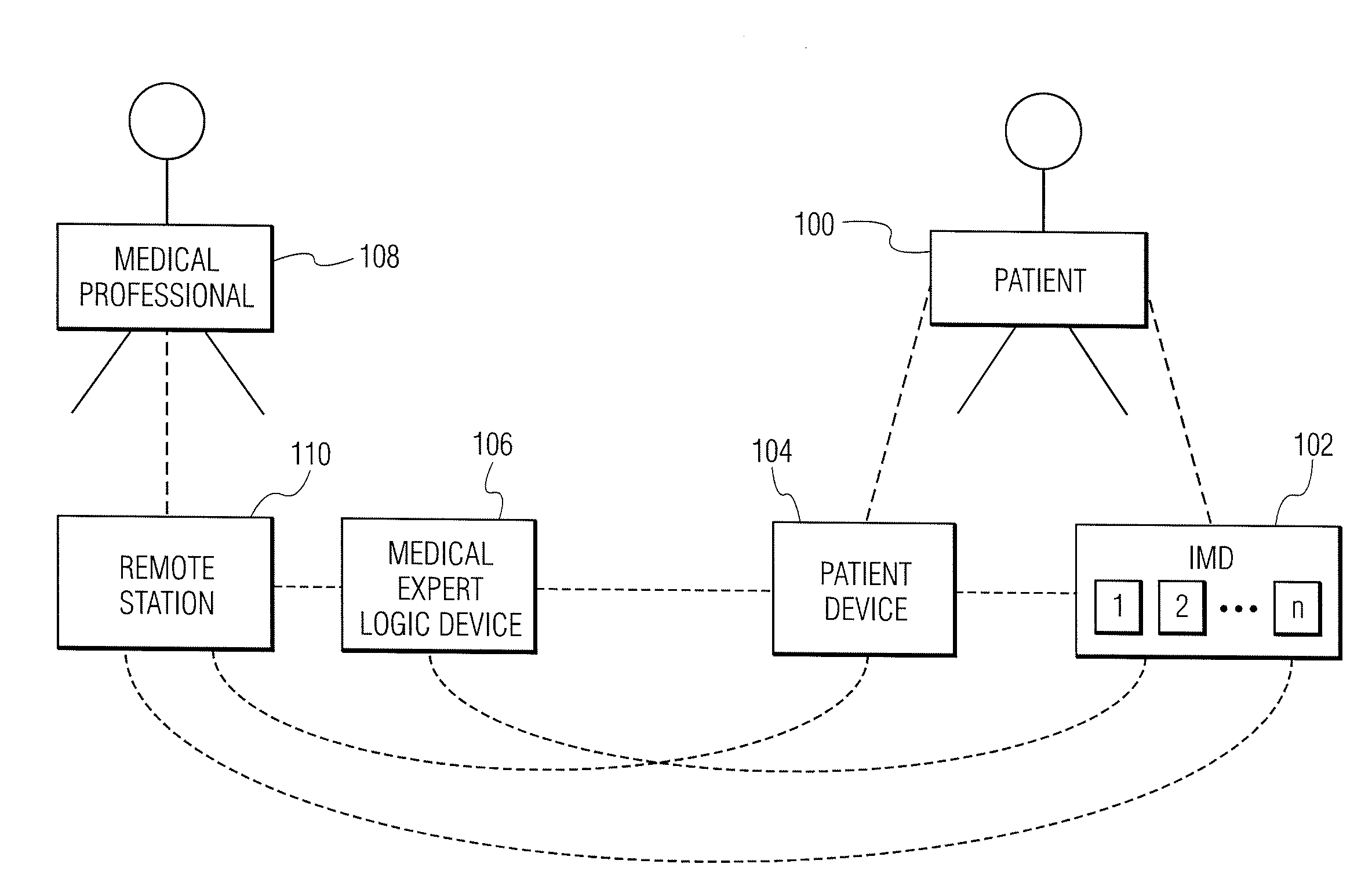
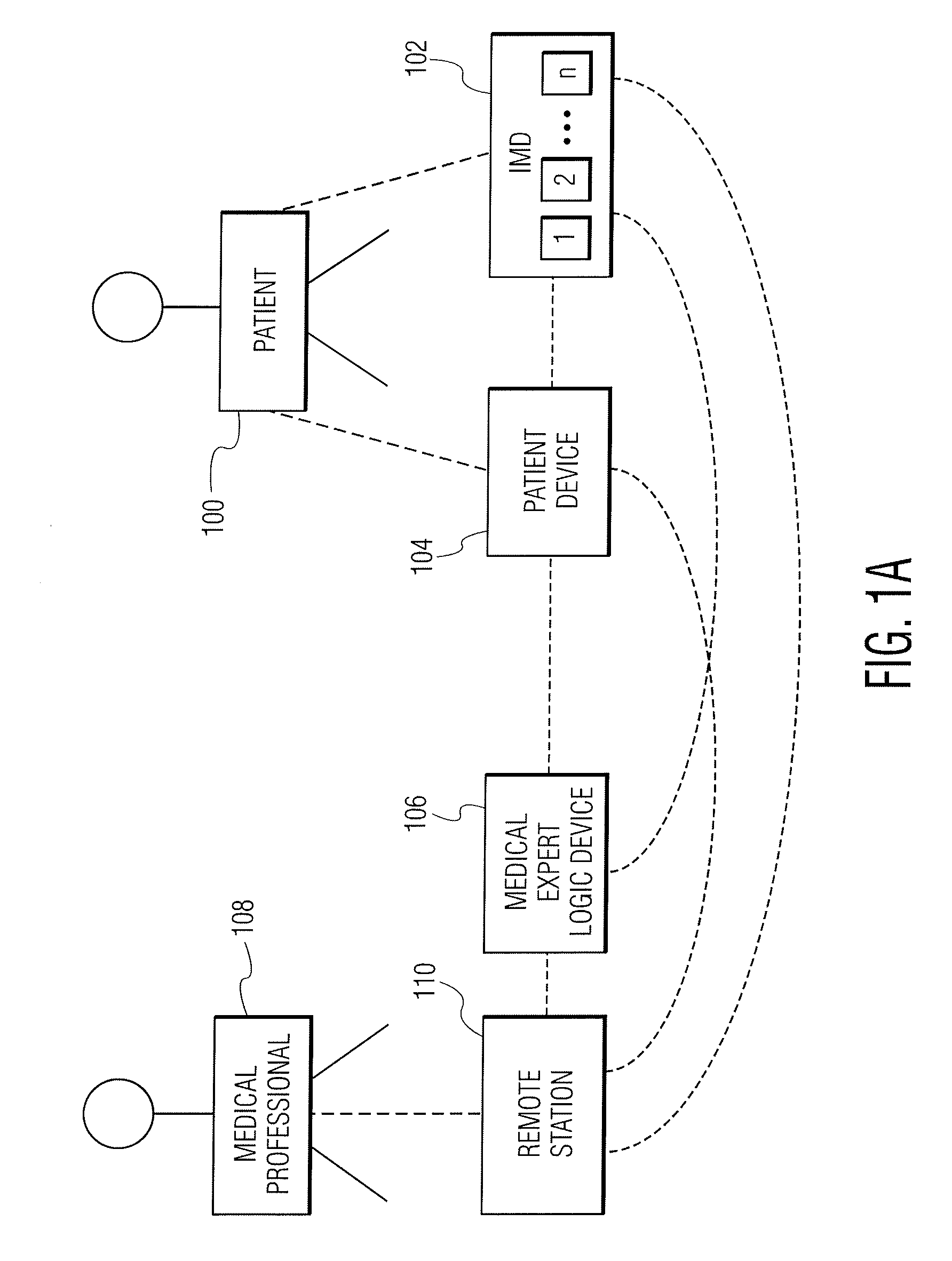
[0065]If yes, who can change them, and how is such a change executed?A structure which allows optional transfer of control involves notifying one entity (e.g. the patient) about the conditions observed by another entity (e.g. the IMD) only under certain circumstances. Thus such notification entails signaling the possible new control source about a patient condition, for which the new control source has the option of taking control. By limiting the conditions for which notification takes place, the patient, other persons and / or devices are not burdened with information about routine matters that the device may easily handle, and the device power supply is not wasted, transmitting unimportant information.
[0080]It is a further object of the current invention to provide a system in which an IMD, a patient device with patient sensors, and a patient can pool their information, to allow for better decision making than would be the case with the use of information coming from only one of the aforementioned three sources. This pooling can be accomplished by:

Problems solved by technology

Implantable medical devices, though they may have complex decision making algorithms do not always make medically optimal decisions.
Some of the time, this is because they do not have access to enough clinical information.
At other times, it may be because they are not optimally programmed.
At still other times, it is because their operating algorithms are not capable of distinguishing between different conditions (e.g. electromagnetic interference vs. broken lead wire vs. life threatening tachycardia, in a patient with an ICD).

Method used


Image

  • Controlling a personal medical device
  • Controlling a personal medical device
  • Controlling a personal medical device

Examples


example b

In Example B, after the two patient shocks, the patient device determines that the patient is uncompromised:

(a) by utilizing information obtained from one or more physiologic sensors, e.g. [i] a blood pressure device (which the patient device might ask the patient to apply); [ii] a sensor for the determination of skin resistance (expected to be elevated if the patient is significantly compromised because of an increase in sympathetic tone associated with the compromised state) and / or [iii] a sensor for one or more of oxygen or carbon dioxide; and / or

(b) by patient interrogation.

When the patient devices makes this determination it signals the ICD to inhibit therapy (the ICD having been programmed to allow such inhibition), and the M.E. device is notified.

At this point, Example A and Example B become identical. The M.E. device, (a) by analyzing signals from the ICD electrograms and / or the analyses of each of the ICD algorithms (transmitted as per FIG. 8), and / or (b) by consulting its e...


PUM


Abstract

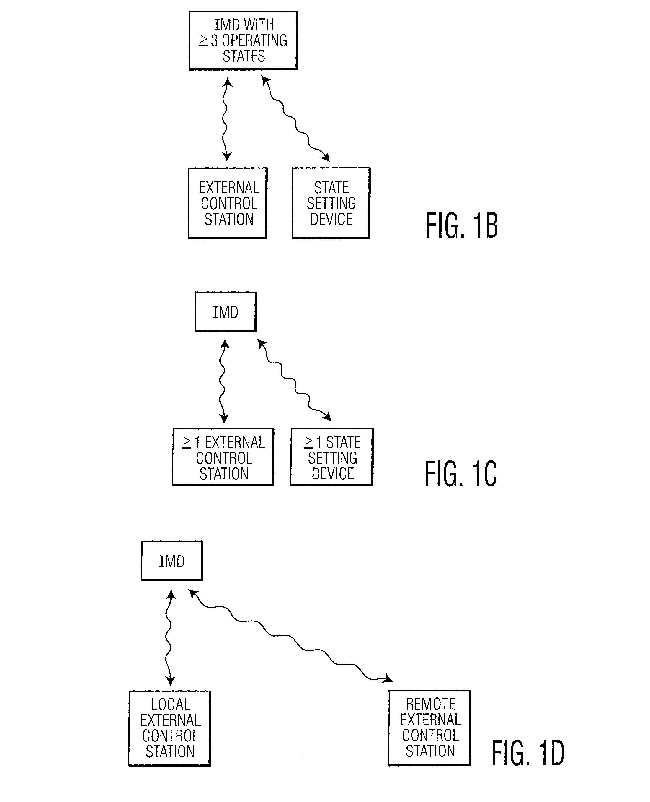
Medical monitoring and treatment apparatus, which is controlled by a plurality of control sources, includes a “personal medical device” (PMD) or an “implantable medical device” (IMD), respectively carried by, or implanted in, a patient. The PMD / IMD is alternatively self-controlled or controlled by one or more local external control stations, at or near the location of the patient, and / or one or more remote external control stations, remote from the patient. Either or both of the local and remote stations may be operated by a person, such as the patient, a patient facilitator and / or a medical professional, or the stations may operate automatically. Since the device is controlled by multiple sources, hierarchies are used to select the source of control.

Description

CROSS-REFERENCE TO RELATED APPLICATIONS[0001]The subject matter of this application is related to that of:[0002]1) U.S. patent application Ser. No. 10 / 460,458, filed Jun. 11, 2003, published on Dec. 18, 2003 as U.S. Patent Publication No. US / 2003 / 0233129, and now U.S. Pat. No. 7,277,752 [provisional application 60 / 387,990 filed on Jun. 11, 2002];[0003]2) U.S. patent application Ser. No. 11 / 502,484, filed Aug. 10, 2006, and published on Feb. 2, 2007 as U.S. Patent Publication No. US / 2007 / 0043585A1 [provisional application 60 / 709,078 filed on Aug. 17, 2005];[0004]3) U.S. patent application Ser. No. 11 / 893,897, filed Aug. 18, 2007, and published on Dec. 27, 2007 as U.S. Patent Publication No. US / 2007 / 0299473 [divisional application of U.S. Pat. No. 7,277,752 cited above];[0005]4) U.S. patent application Ser. No. 11 / 895,934, filed Aug. 28, 2007, and published on Mar. 6, 2008 as U.S. Patent Publication No. US / 2008 / 0058884 [provisional application 60 / 840,722 filed on Aug. 29, 2006, provis...

Claims


Application Information

Patent Timeline
IPC IPC(8): A61N1/08
CPCA61B5/0816G06F19/3481A61B5/14542A61M5/14276A61M5/1723A61M2205/3553A61M2230/201A61N1/3621A61N1/37235A61N1/37247A61N1/37252A61N1/37258A61N1/37282A61N1/37288A61N1/3962G06F19/3406A61B5/0836G16H40/63A61N1/39622G16H40/67G16H10/60H04B17/309A61N1/362A61N1/3956H04L1/0003H04L1/0013H04L1/0015H04L1/0026H04W4/023H04W24/02A61M2205/3592A61M2205/52A61N1/37217A61N1/37264
Inventor MATOS, JEFFREY A.
Owner MATOS JEFFREY A
Learn More