System Unit For A Computer

a computer and system technology, applied in the field of system units for computers, can solve problems such as the reduction of the ventilator speed of the controller, and achieve the effect of improving the cooling of the computer

Active Publication Date: 2010-10-21
SIEMENS AG
View PDF18 Cites 4 Cited by
  • Summary
  • Abstract
  • Description
  • Claims
  • Application Information

AI Technical Summary

Benefits of technology

[0005]It is therefore an object of the present invention to provide a system unit for improving the cooling of a c

Problems solved by technology

For example, in the event that a vertical installation of the system unit in a switchgear cabinet is thermally

Method used


Image

  • System Unit For A Computer
  • System Unit For A Computer

Examples


Embodiment Construction

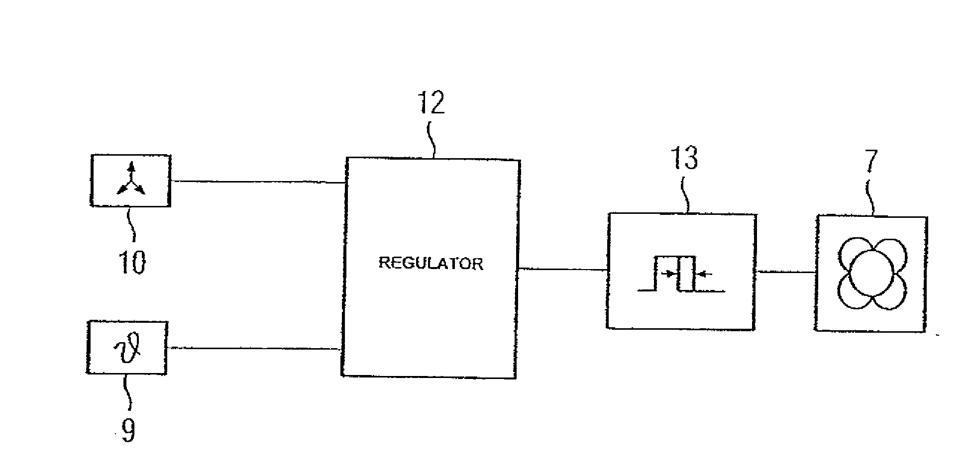
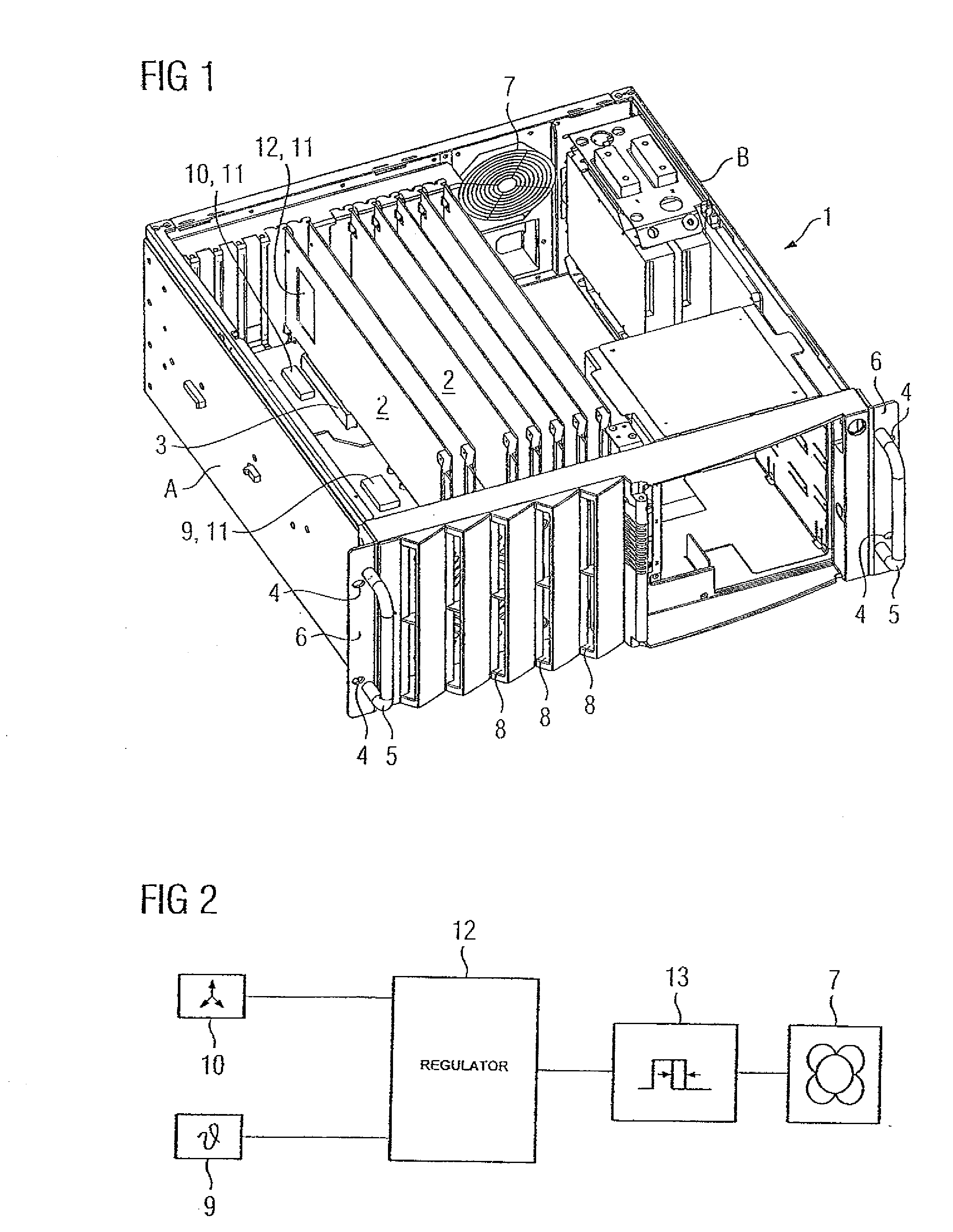
[0013]The same parts shown in FIGS. 1 and 2 are provided with the same reference characters. With specific reference to FIG. 1, a system unit 1 of a computer is shown without a cover and without installed floppy disks or hard disk devices. Control input units, such as control input units comprising a keyboard and / or a mouse, as well as at least one image reproduction device and further hardware units can be connected to this system unit 1. The system unit 1 is also provided with so-called PCI plug-in cards 2, which are shown plugged into slots 3 of a motherboard.

[0014]It is to be readily understood that the motherboard includes additional slots for receiving additional PCI plug-in cards, such as plug-in cards for implementing Ethernet or field bus communication. Two mounting brackets 6 are provided with holes 4 and handles 5 and are arranged on the front of the system unit 1, by which the system unit 1, for example, can either be integrated horizontally or vertically in a switchgear...


PUM


Abstract

A system unit for a computer comprising at least one plug-in card provided with components and a ventilator for cooling the components, wherein the system unit is also provided with a controller for setting the ventilator speed as a function of a signal of a temperature sensor. Measures are provided which, irrespective of whether the system unit is integrated in a horizontal or vertical position, such as in a switchgear cabinet, effect a good level of cooling.

Description

BACKGROUND OF THE INVENTION[0001]The invention relates to a system unit for a computer comprising at least one plug-in card provided with components and a ventilator for cooling the components, where the system unit is also provided with a controller for setting the ventilator speed as a function of a signal of a temperature sensor.[0002]Siemens catalog ST PCT, issue November 2008, chapter 3 discloses a conventional system unit of a computer. A control input unit, such as a control input unit comprises a keyboard and / or mouse, as well as at least one display device and other hardware units can be connected to this system unit in the form of a so-called “Rack PC”. This system unit is additionally provided with further PCI plug-in cards, and other hardware means, which can be plugged into slots of a motherboard and which are also suited to operate the computer. An airflow generated by a ventilator is provided for cooling the PCI plug-in cards and / or their components, with a controller...

Claims


Application Information

Patent Timeline
IPC IPC(8): G05D23/19
CPCG06F1/206H05K7/207H05K7/20563
Inventor BERZ, ARNOSPUHLER, BERNHARD
Owner SIEMENS AG
Why Eureka
Try Eureka