Shoe tying aid and method

a shoe lace and shoe technology, applied in the field of shoe lace tying aids and methods, can solve the problems of lost hand use, inability to tie shoes by themselves, and lack of manual dexterity of young children to tie shoes, etc., and achieve the effect of simple and effectiv

Inactive Publication Date: 2010-10-28
THERM OMEGA TECH INC
View PDF22 Cites 32 Cited by
  • Summary
  • Abstract
  • Description
  • Claims
  • Application Information

AI Technical Summary

Benefits of technology

[0004]This invention affords a simple and effective way for an individual to tie a shoe with only one hand, and also makes it po

Problems solved by technology

This means that individuals who have lost the use of one hand through injury, because of a stroke, or as a result of some other

Method used


Image

  • Shoe tying aid and method
  • Shoe tying aid and method
  • Shoe tying aid and method

Examples


Embodiment Construction

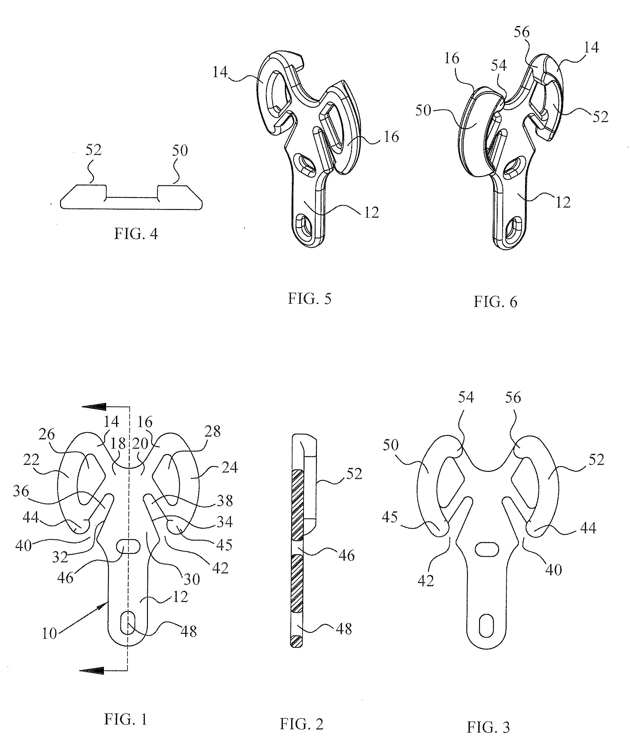
[0026]As mentioned above, the invention is practiced by the use of a tying aid. The tying aid 10, shown in FIGS. 1-6 is preferably a unitary, substantially rigid, element molded from a suitable low friction polymer such as recycled ABS (acrylonitrile butadiene styrene) or recycled polycarbonate. It comprises a leg 12 having ears 14 and 16 protruding laterally from one of its ends. The ears have narrow inner parts 18 and 20 connected to the leg, and larger outer parts 22 and 24. For weight reduction, the ears can be formed with openings 26 and 28.

[0027]The leg is formed with a tapered portion 30 which extends from a location at which it meets the narrow parts 18 and 20 of said ears toward the end of the leg remote from the ears. The side edges 32 and 34 of portion 30 of the leg diverge with respect to each other from the location at which it meets the narrow parts of the ears. An oblique slot 36 is formed between side edge 32 and ear 14, and a similar oblique slot 38 is formed betwee...


PUM


Abstract

A shoe can be tied using only one hand if provided with a tying aid in the form of a generally T-shaped unit comprising a leg having two laterally extending ears. The leg is secured between rows of eyelets on the opposed flaps of the shoe by one or more of the lengths of lace extending across the gap between the flaps. The lengths of shoelace that would otherwise be tied in a bow are instead wrapped around the ears of the tying aid in alternating fashion, preferably twice around each ear, in a manner similar to the manner in which a mooring line is secured to the cleat of a boat.

Description

FIELD OF THE INVENTION[0001]This invention relates to footwear, and more particularly to a device for assisting an individual in tying a shoe and a method for tying a shoe.BACKGROUND OF THE INVENTION[0002]A conventional shoe utilizing a shoelace, has rows of eyelets on opposed flaps overlying a tongue. The shoelace is threaded back and forth from one row of eyelets to the other. When the end portions of the shoelace, protruding through the endmost eyelets remote from the toe of the shoe, are pulled, the flaps are drawn toward each other by tension in the portions of the shoelace bridging the gap between the flaps. The end portions are then tied, typically by forming an overhand knot and a bow. Usually the bow is one that can be released simply by pulling on one of the ends of the shoelace. A more secure bow can be formed by forming two loops in the sections of lace extending from the overhand knot and tying the two loops in another overhand knot. Various other shoelace tying techniq...

Claims


Application Information

Patent Timeline
IPC IPC(8): A43B23/00B65H69/00A43C11/00
CPCY10T24/3703A43C7/00
Inventor PIRKLE, FRED L.OWENS, TIMOTHY L.
Owner THERM OMEGA TECH INC
Why Eureka
Try Eureka