Power Threading and Cutting Device with Sliding Support

a cutting device and sliding support technology, applied in the field of pipe threading, to achieve the effect of improving operation speed, improving convenience, and increasing user's productivity

Inactive Publication Date: 2010-10-28
RANTZ GORDON
View PDF73 Cites 6 Cited by
  • Summary
  • Abstract
  • Description
  • Claims
  • Application Information

AI Technical Summary

Benefits of technology

[0012]The power threading and cutting device of the present invention provides improved convenience such that users will prefer to use the invention, even when threading or cutting small work pieces such as small diameter pipe (pipe less than 1″ in diameter). The device of the present invention only requires one hand to use. Normally, a user would use two hands just to manage the torque and weight of the power drive. This is a problem because properly threading pipe requires lubricatin...

Problems solved by technology

This is a problem because properly threading pipe requires lubricat...

Method used


Image

  • Power Threading and Cutting Device with Sliding Support
  • Power Threading and Cutting Device with Sliding Support
  • Power Threading and Cutting Device with Sliding Support

Examples


Embodiment Construction

briefly described above will be rendered by reference to specific embodiments that are illustrated in the appended drawings. Understanding that these drawings depict only typical embodiments of the invention and are not therefore to be considered limiting of its scope, the invention will be described and explained with additional specificity and detail through the use of the accompanying drawings, in which:

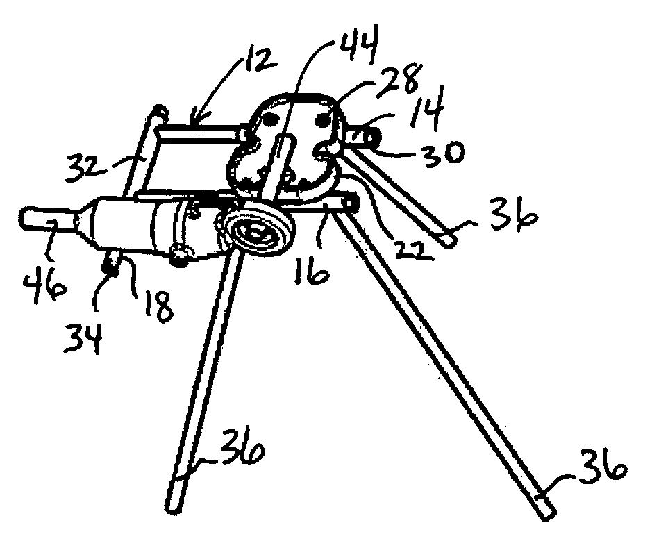
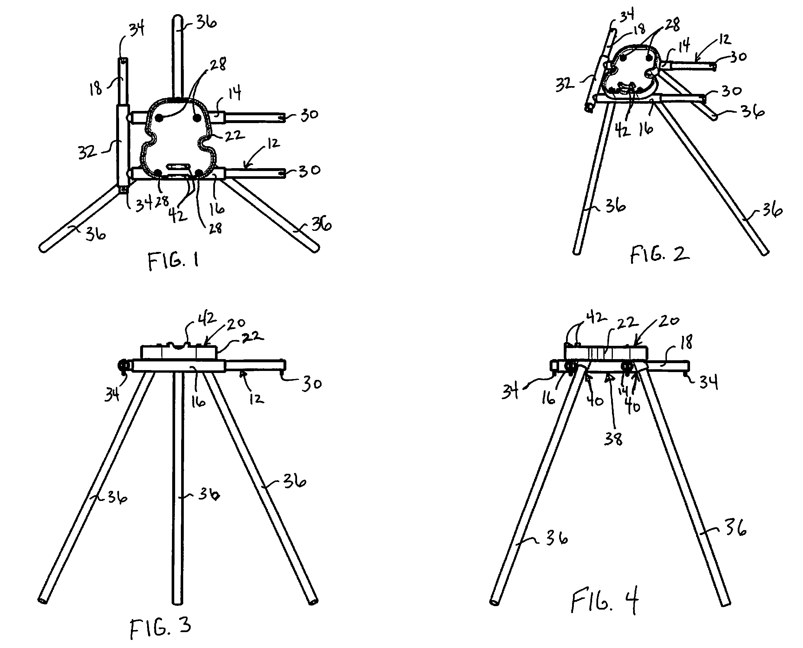
[0021]FIG. 1 is a top view of one embodiment of a power threading and cutting device in accordance with the present invention;

[0022]FIG. 2 a side perspective view of the power threading and cutting device of FIG. 1;

[0023]FIG. 3 a front view of the power threading and cutting device illustrated in

[0024]FIG. 1;

[0025]FIG. 4 a right side view of the power threading and cutting device illustrated in FIG. 1;

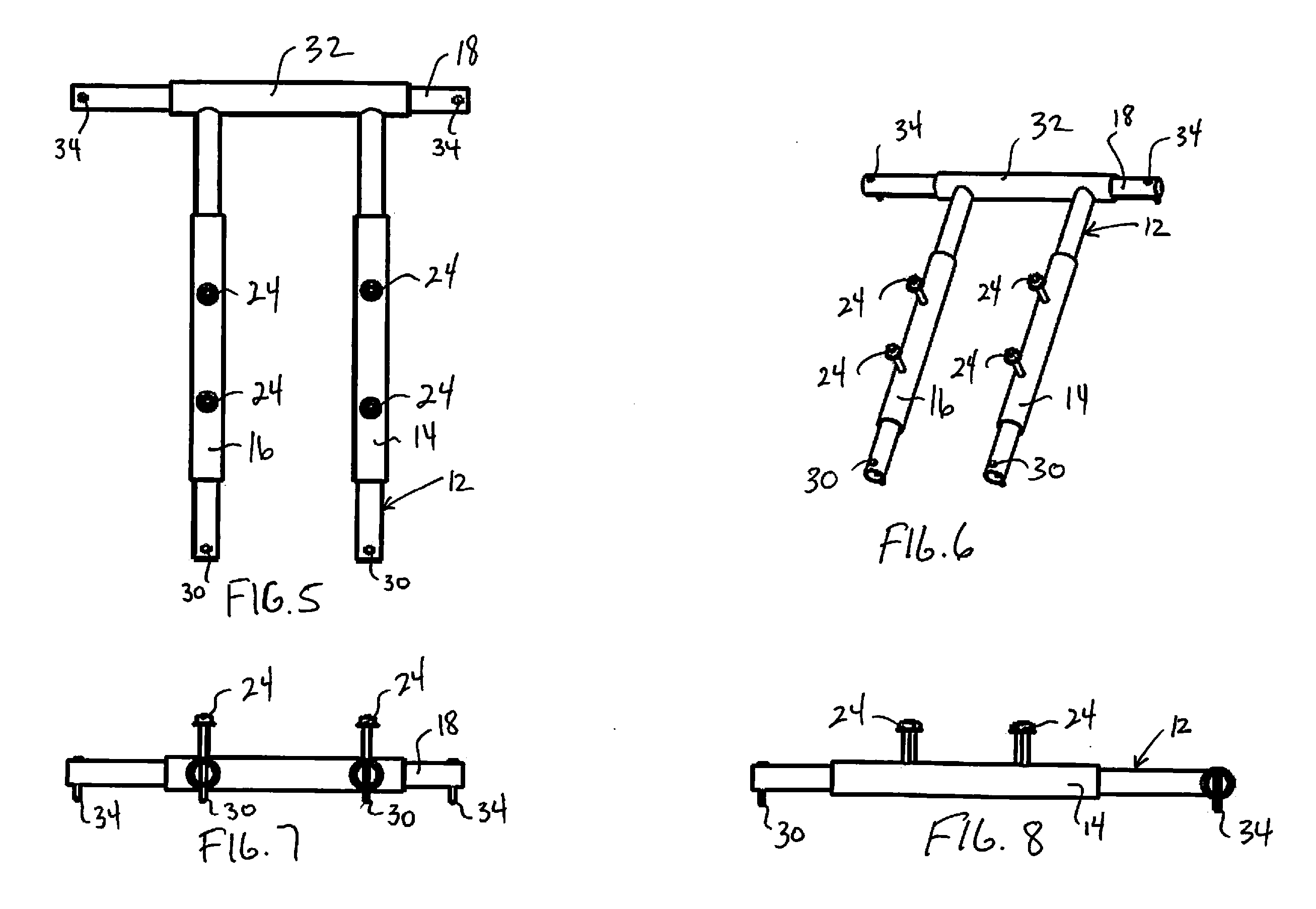
[0026]FIG. 5 a top view of the support arm of power threading and cutting device illustrated in FIG. 1;

[0027]FIG. 6 a side perspective view of the support arm illustrated in FIG. 5;

[...


PUM

PropertyMeasurementUnit
Lengthaaaaaaaaaa
Forceaaaaaaaaaa
Areaaaaaaaaaaa

Abstract

An adjustable support for supporting power threading and cutting devices is provided. The support includes an elevated stand adapted for holding a work piece, a support member and an adjustable bracket mounted to the elevated stand. The adjustable bracket is configured to receive the support member whereby the support member is free to move longitudinally and laterally with respect to the work piece so that the support member can be positioned either distal or proximal to a front end of the elevated stand. The support arm may be a support arm which is secured to the elevated stand and slidably received along an axis parallel to the work piece. A power threading and cutting device having a powered element to engage a work piece and a support adjustable in at least two axes parallel to the work piece is also contemplated. The adjustable support may be conveniently moved out of the operational area when it is not in use.

Description

RELATED APPLICATION[0001]This application is based on U.S. Provisional Application 61 / 173,576, filed on Apr. 28, 2009.FIELD OF THE INVENTION[0002]The invention pertains to pipe threading and the related tools and methods and particularly, portable powered threading and cutting devices used in conjunction with a portable vise. More particularly, positionable support arms for use with threading and cutting devices for threading or cutting work pieces including 1″ and larger diameter pipes.BACKGROUND OF THE INVENTION[0003]The task of threading and cutting work pieces including pipe larger than 1″ in diameter with a portable power drive exposes the user to risk of bodily harm. When a user attempts to thread large work piece or large diameter pipe with a portable power drive and a pipe vise with no additional tools, the torque generated is difficult to manage. If the power drive gets away from the user, the rotational acceleration of the tool generates momentum that could easily injure a...

Claims


Application Information

Patent Timeline
IPC IPC(8): B23G1/52B23G1/24F16M11/04
CPCB23G1/24Y10T82/22B23G1/52B25H1/06B25H1/08
Inventor RANTZ, GORDON
Owner RANTZ GORDON
Why Eureka
Try Eureka