Apparatus and method of perforating a component

a technology of apparatus and component, applied in the direction of metal working apparatus, etc., can solve the problems of inflexibility and large space requirements of the punching machine, and achieve the flexibility of the apparatus, shorten the cycle time, and facilitate the retrofit

Inactive Publication Date: 2010-10-28
BENTELER MASCHENBAU
View PDF8 Cites 0 Cited by
  • Summary
  • Abstract
  • Description
  • Claims
  • Application Information

AI Technical Summary

Benefits of technology

[0007]According to another advantageous feature of the present invention, the hole punch may be configured to include exchangeable punching tools for producing holes in the component. These punching tools may be exchanged automatically, for example via a quick change system. In this way, the desired hole size can be quickly and automatically realized.
[0018]The use of a robotic arm for perforating components is also advantageous because of the attained flexibility of the apparatus. For example, adapters can be exchanged so that the robotic arm can be easily retrofitted for other manipulations in addition to punching holes. Depending on need, various processing steps can be executed in one station.

Problems solved by technology

Such a punching machine requires much space and is inflexible because the stroke direction is predefined.

Method used


Image

  • Apparatus and method of perforating a component
  • Apparatus and method of perforating a component
  • Apparatus and method of perforating a component

Examples


Embodiment Construction

[0024]Throughout all the figures, same or corresponding elements may generally be indicated by same reference numerals. These depicted embodiments are to be understood as illustrative of the invention and not as limiting in any way. It should also be understood that the figures are not necessarily to scale and that the embodiments are sometimes illustrated by graphic symbols, phantom lines, diagrammatic representations and fragmentary views. In certain instances, details which are not necessary for an understanding of the present invention or which render other details difficult to perceive may have been omitted.

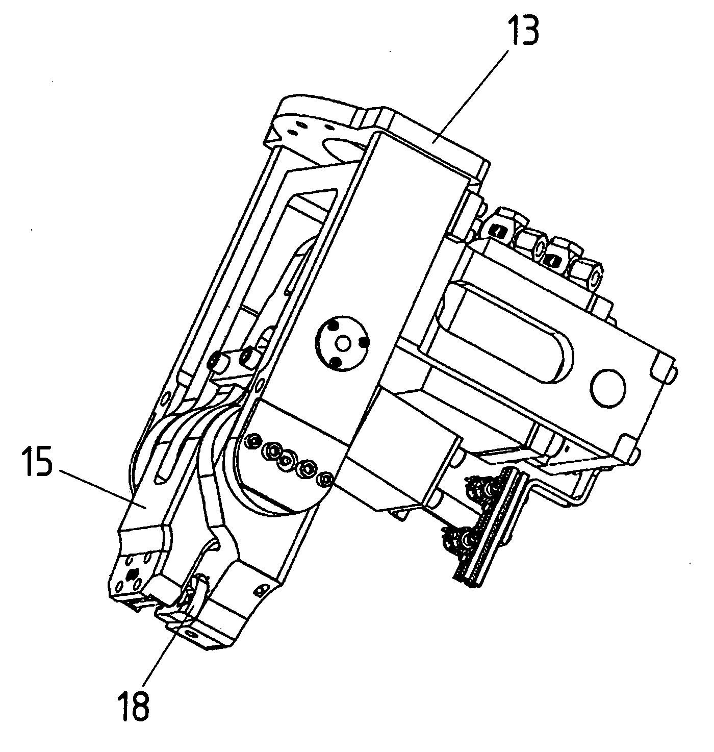
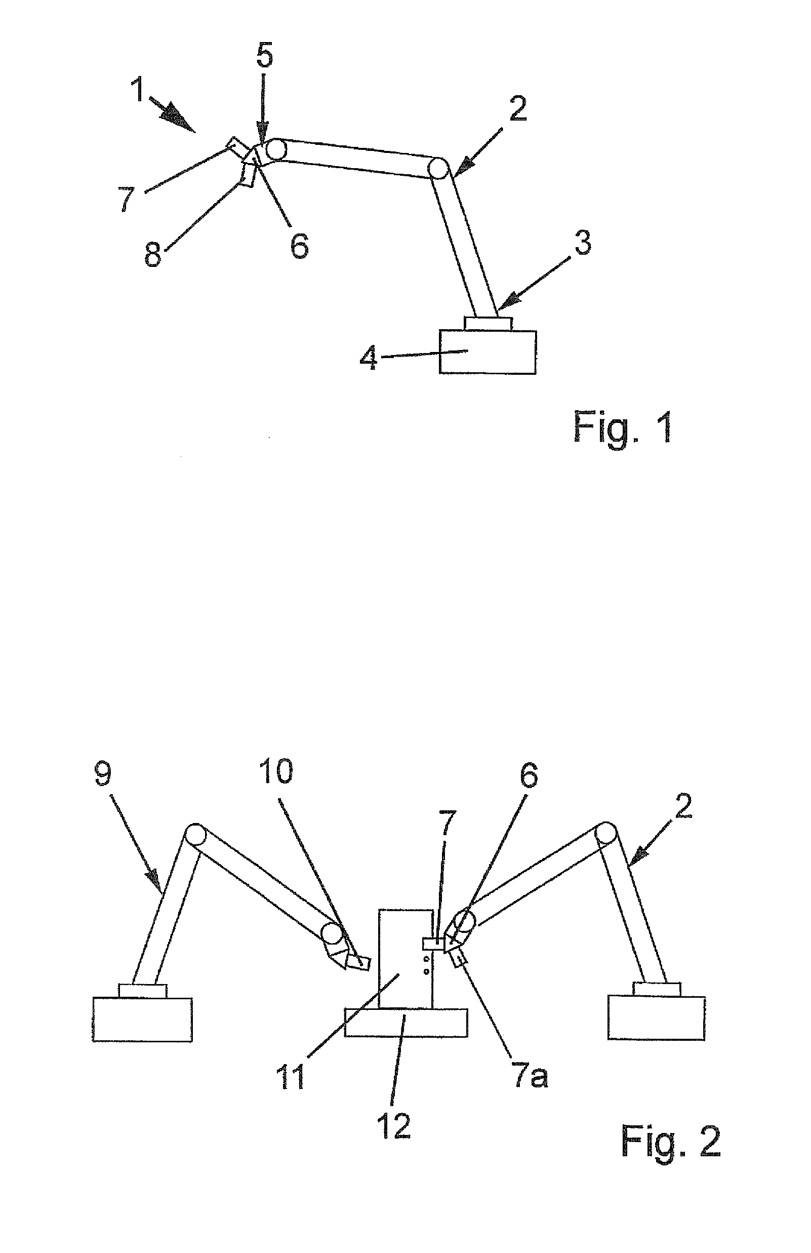
[0025]Turning now to the drawing, and in particular to FIG. 1, there is shown a schematic illustration of an apparatus, generally designated by reference numeral 1, for perforating a component, also referred to as workpiece. The apparatus 1 includes a robot system having a robotic arm 2. It will be appreciated by persons skilled in the art that the robot system must contain ...


PUM

PropertyMeasurementUnit
hole sizeaaaaaaaaaa
sizesaaaaaaaaaa
sizeaaaaaaaaaa

Abstract

Apparatus for perforating a component includes at least one robotic arm having a free end for securement of an adapter. At least one hole punch is coupled by the adapter to the robotic arm. The adapter can be configured in one of two ways, a first way in which the adapter supports a component gripper in addition to the hole punch, a second way in which the adapter supports a further hole punch in addition to the one hole punch.

Description

CROSS-REFERENCES TO RELATED APPLICATIONS[0001]This application claims the priority of German Patent Application, Serial No. 10 2009 017 972.0, filed Apr. 21, 2009, pursuant to 35 U.S.C. 119(a)-(d), the content of which is incorporated herein by reference in its entirety as if fully set forth herein.BACKGROUND OF THE INVENTION[0002]The present invention relates, in general, to an apparatus and method of perforating a component.[0003]The following discussion of related art is provided to assist the reader in understanding the advantages of the invention, and is not to be construed as an admission that this related art is prior art to this invention.[0004]Shear cutting has been used to punch one or more holes in a workpiece. The punching process typically is executed on a stationary punching machine to which the workpiece to be machined is fed. Such a punching machine requires much space and is inflexible because the stroke direction is predefined.[0005]It would therefore be desirable ...

Claims


Application Information

Patent Timeline
Patent Type & Authority Applications(United States)
IPC IPC(8): B26F1/00B26D5/08
CPCB21D28/26B26F1/02B26D7/0633Y10T83/869Y10T83/0481Y10T83/8727
Inventor BECKER, KARSTEN
Owner BENTELER MASCHENBAU
Why Eureka
Try Eureka