Conveyor chain and conveyor for gripping and conveying paper material

a conveyor chain and paper material technology, applied in the direction of pile separation, lighting and heating apparatus, furnace components, etc., can solve the problems of high cost, complicated chain manufacturing, and relatively noisy circulation of steel chains, and achieve the effect of low cos

Active Publication Date: 2010-10-28
NEOPOST TECH SA
View PDF13 Cites 8 Cited by
  • Summary
  • Abstract
  • Description
  • Claims
  • Application Information

AI Technical Summary

Benefits of technology

[0005]It is an object of the present invention to provide a low cost, yet durable solution for reliably gripping sheets, conveying the gripped sheets along a path and releasing the conveyed sheets.

Problems solved by technology

A disadvantage of such a chain is that manufacturing of the chain is quite complicated and accordingly costly.
Moreover, steel chains tend to be relatively noisy when circulating in operation, which is a particular disadvantage if the conveyor is to be used in or close to an office environment.
While manufacturing costs of such belts appear to be lower than the manufacturing costs of chains equipped with grippers, engagement of the sheets tends to be less positive and relatively much friction is involved in controlling flaps of the belts for gripping and releasing sheets when required.

Method used


Image

  • Conveyor chain and conveyor for gripping and conveying paper material
  • Conveyor chain and conveyor for gripping and conveying paper material
  • Conveyor chain and conveyor for gripping and conveying paper material

Examples


Embodiment Construction

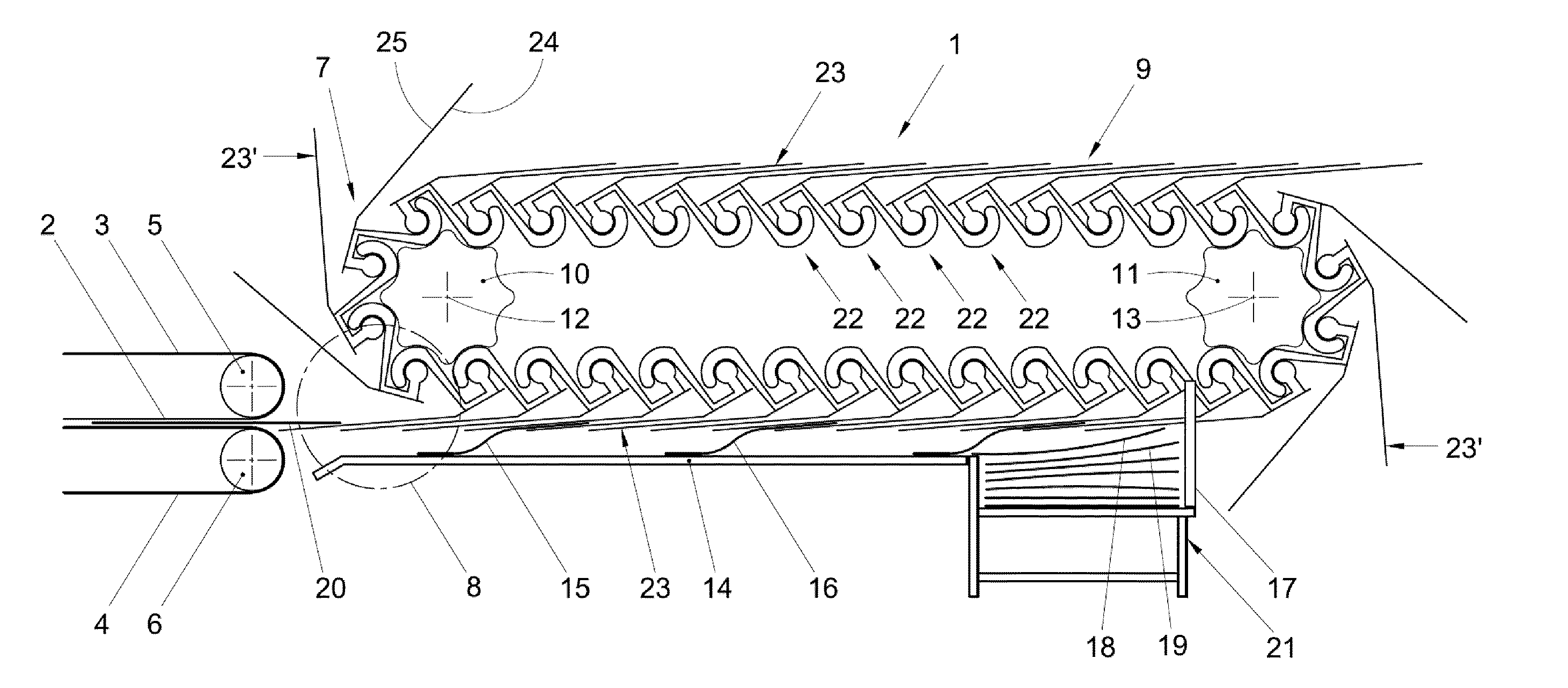
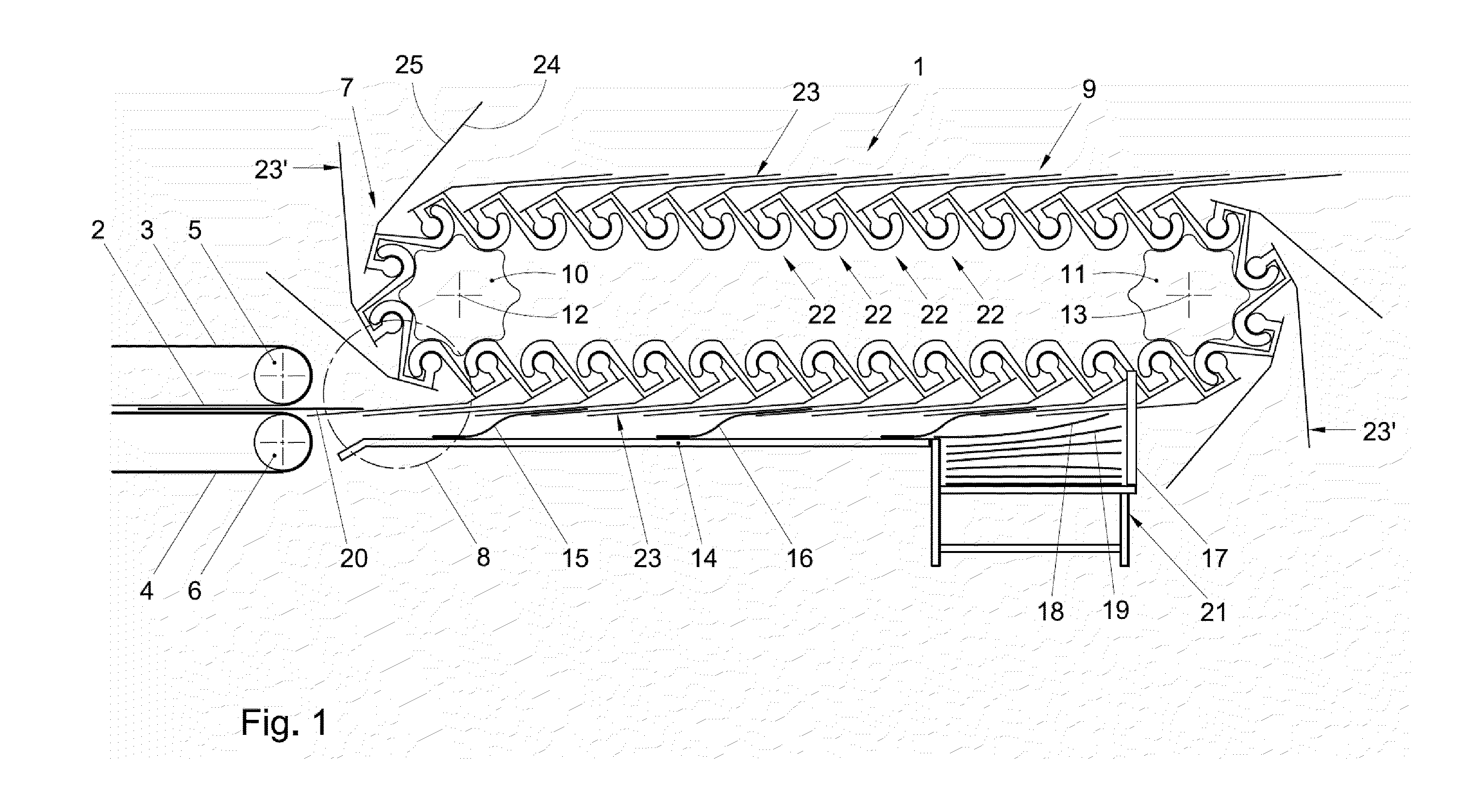
[0016]In FIG. 1, an example of a collator equipped with an example of a conveyor 1 according to the invention is shown. The collator has a feed path 2 between opposite belts 3, 4 (partially shown only) arranged for circulation about rotatable disks 5, 6. A downstream end of the feed path 2 converges with a conveyor chain path 7 in a grip area 8 of the conveyor chain path 7. A chain 9 is supported in a configuration defining the chain path 7, by a chain support structure constituted by sprocket wheels 10, 11 rotatably suspended and driven for rotation about axes 12, 13 perpendicular to a plane in which the chain path 7 extends.

[0017]Under a lower portion of the chain path 7, a sheet guide 14 is arranged for guiding tail portions of sheets 15, 16 gripped by the chain 9. Downstream of the sheet guide 14, an abutment 17 is arranged, in the path of the sheets 15, 16 entrained by the chain 9. A sheet 18 is shown in a position abutting the abutment 17. The abutment 17 stops the sheet 18 an...


PUM


Abstract

A conveyor chain for gripping and conveying paper material has a plurality of links hingedly connected to each other. At least one of the links has a grip arm having a first grip surface. The grip arm is movable back and forth relative to a second grip surface of the chain between a grip position for holding paper material and a retracted position for insertion of the paper material between the first and second grip surfaces. The links are molded of plastic material. The or each grip arm is an integrally molded portion of one of the links. A conveyor including such a chain is also described.

Description

FIELD AND BACKGROUND OF THE INVENTION[0001]The invention relates to a conveyor chain and a conveyor for gripping and conveying paper material.[0002]In U.S. Pat. No. 6,241,648, a conveyor chain composed of hingedly connected links is disclosed of which some of the links each have a first grip member having a first grip surface. The first grip members are each movable back and forth relative to a second grip member between a gripping position for holding paper material and a retracted position for releasing the paper material. The first grip members are formed of spring-steel plate and the second grip members are made of a plate material harder than the plate material of the first grip member.[0003]A disadvantage of such a chain is that manufacturing of the chain is quite complicated and accordingly costly. Moreover, steel chains tend to be relatively noisy when circulating in operation, which is a particular disadvantage if the conveyor is to be used in or close to an office environm...

Claims


Application Information

Patent Timeline
Patent Type & Authority Applications(United States)
IPC IPC(8): B65G17/32B65G17/16
CPCB65G17/326B65G17/38B65G57/11B65H2405/575B65H29/048B65H2401/11B65H2404/31B65H29/041
Inventor BIJL, ERIK JOUKE
Owner NEOPOST TECH SA
Why Eureka
Try Eureka