Shale shaker

a shaker and shaker technology, applied in the direction of filtration separation, separation process, moving filter element filter, etc., can solve the problem of wear screening material out quickly, and achieve the effect of inhibiting vibration and facilitating solids flow

Active Publication Date: 2010-10-28
NAT OILWELL VARCO LP
View PDF104 Cites 64 Cited by
  • Summary
  • Abstract
  • Description
  • Claims
  • Application Information

AI Technical Summary

Benefits of technology

[0030]Preferably, the basket further comprises a trough, wherein the at least one first screen deck has a solids discharge end and the trough is arranged thereunder to receive solids. Preferably the trough is made from a composite material, although it may be made from a sheet steel or other metal or plastics material. Preferably, the shale shaker further comprises a sump arranged below the basket, the tough arranged to feed solids into the sump. Advantageously, the basket further comprising a jetting nozzle arranged to jet screened drilling fluid into the trough to facilitate flow of solids therethrough.
[0031]Preferably, the basket further comprises a flexible duct, solids flowing through the trough into the flexible duct and into the sump. The flexible duct preferably leads from a side wall of the basket to a sump arranged therebelow, the flexible duct allowing the basket to isolate the basket from the base to inhibit vibrations passing to the base.

Problems solved by technology

An overflow from a weir tends to contain more fluid and low density solids and the fluid left in behind the weir tends to contain high density solids, which tend to be sharp and aggressive which wear screening material out quickly.

Method used


Image

  • Shale shaker
  • Shale shaker
  • Shale shaker

Examples


Embodiment Construction

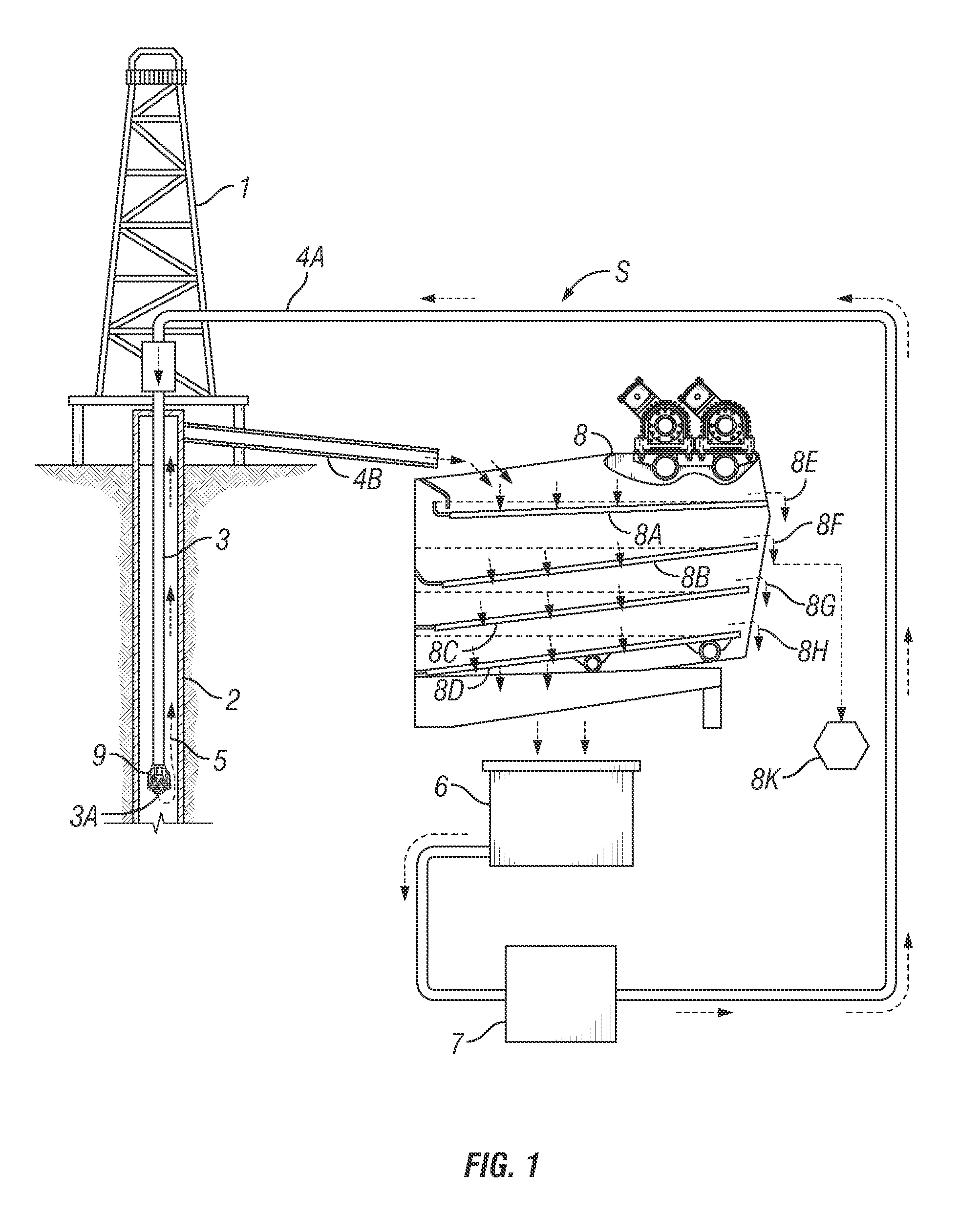
[0132]FIG. 1 illustrates a system S according to the present invention which includes a derrick 1 that extends vertically over a wellbore 2. A tubular work string 3 extends into the wellbore 2, and extends from the earth's surface to a desired depth within the wellbore. A flow line 4a is connected to the tubular work string 3. A flow line 4b is connected to annular space 5 formed between the outer surface of tubular work string 3 and the inner surface of wellbore 2. Drilling fluid (or “mud”) for the system in a mud pit 6 is circulated through the overall mud system via a mud pump 7. During typical drilling operations, fluid is pumped into the tubular work string 3 by the mud pump 7 through the flow line 4a, circulated out a bottom end 3a of the tubular work string 3 (e.g., but not limited to, out from a drill bit 9), up an annulus 5 of the wellbore 2, and out of the annulus 5 via the flow line 4b.

[0133]Spent (or used) fluid mud exiting the wellbore annulus 5 through the flow line 4...


PUM

PropertyMeasurementUnit
angleaaaaaaaaaa
angleaaaaaaaaaa
heightsaaaaaaaaaa

Abstract

A shale shaker for separating solids from solids laden drilling fluid is disclosed as having a basket with a scalping screen deck, at least one first screen deck and at least one second screen deck. The basket further may have a flow tray arranged between said scalping screen deck and at least one first screen deck, and a plurality of first ducts and a plurality of second ducts, the plurality of first ducts for directing solids laden drilling fluid to the at least one first screen deck. The second plurality of second ducts are for directing solids laden drilling fluid to said second screen deck.

Description

CROSS-REFERENCE TO RELATED APPLICATIONS[0001]This Application is a continuation-in-part of Ser. No. 12 / 490,492 filed on Jun. 24, 2009 entitled “Shale Shaker flow Diverter”, which is a continuation-in-part of U.S. application Ser. No. 12 / 287,709 filed on Oct. 10, 2008 entitled “Systems and Methods For the Recovery of Lost Circulation and Similar Material” both of which are incorporated by reference herein for all they disclose.BACKGROUND OF THE INVENTION[0002]1. Field of the Invention[0003]The present invention is directed to drilling fluid processing systems; shale shakers; to methods for using these things; and, in certain particular aspects, to shale shakers with structure for converting shaker fluid flow paths from series to parallel, and vice versa.[0004]2. Description of the Related Art[0005]In the oil and gas industries, shale shakers use screens to treat drilling fluid contaminated with undesirable solids. Typically such apparatuses have a basket, deck, or other screen holdin...

Claims


Application Information

Patent Timeline
Patent Type & Authority Applications(United States)
IPC IPC(8): B07B1/00B07B1/46B07B1/04
CPCB01D33/0376B07B1/46B07B13/16B07B2201/04B07B2230/01B01D33/41
Inventor BURNETT, GEORGE ALEXANDERLARSON, THOMAS ROBERT
Owner NAT OILWELL VARCO LP
Why Eureka
Try Eureka