Lens position sensor for infrared cameras

a technology of infrared cameras and lens positions, applied in the field of infrared camera lens positions sensors, can solve the problems of resolution and therefore the accuracy of lens position sensors in such instances may be compromised, and the short axial translation does not provide much axial translation

Active Publication Date: 2010-10-28
JOHN FLUKE MFG CO INC
View PDF5 Cites 25 Cited by
  • Summary
  • Abstract
  • Description
  • Claims
  • Application Information

AI Technical Summary

Problems solved by technology

The short axial translation does not provide much axial translation over which lens position sensors may be used to measure the f...

Method used


Image

  • Lens position sensor for infrared cameras
  • Lens position sensor for infrared cameras
  • Lens position sensor for infrared cameras

Examples


Embodiment Construction

[0021]The following detailed description is exemplary in nature and is not intended to limit the scope, applicability, or configuration of the invention in any way. Rather, the following description provides practical illustrations for implementing exemplary embodiments of the invention.

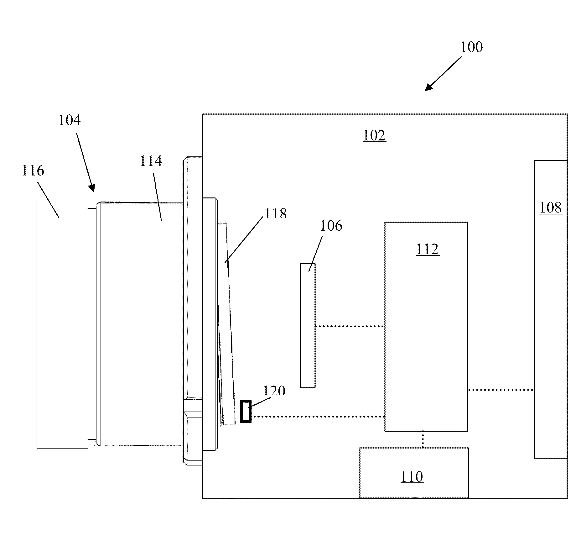
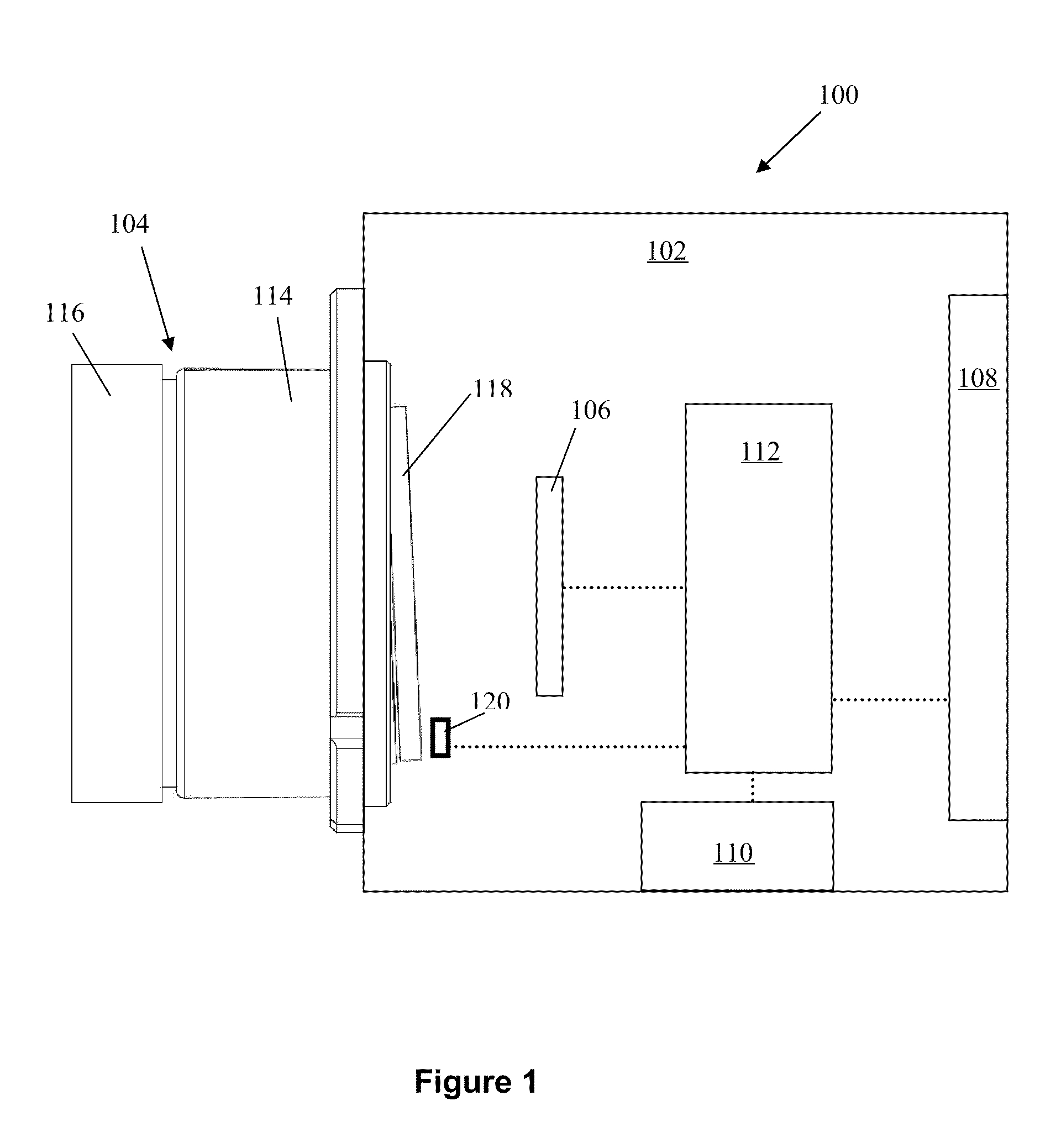
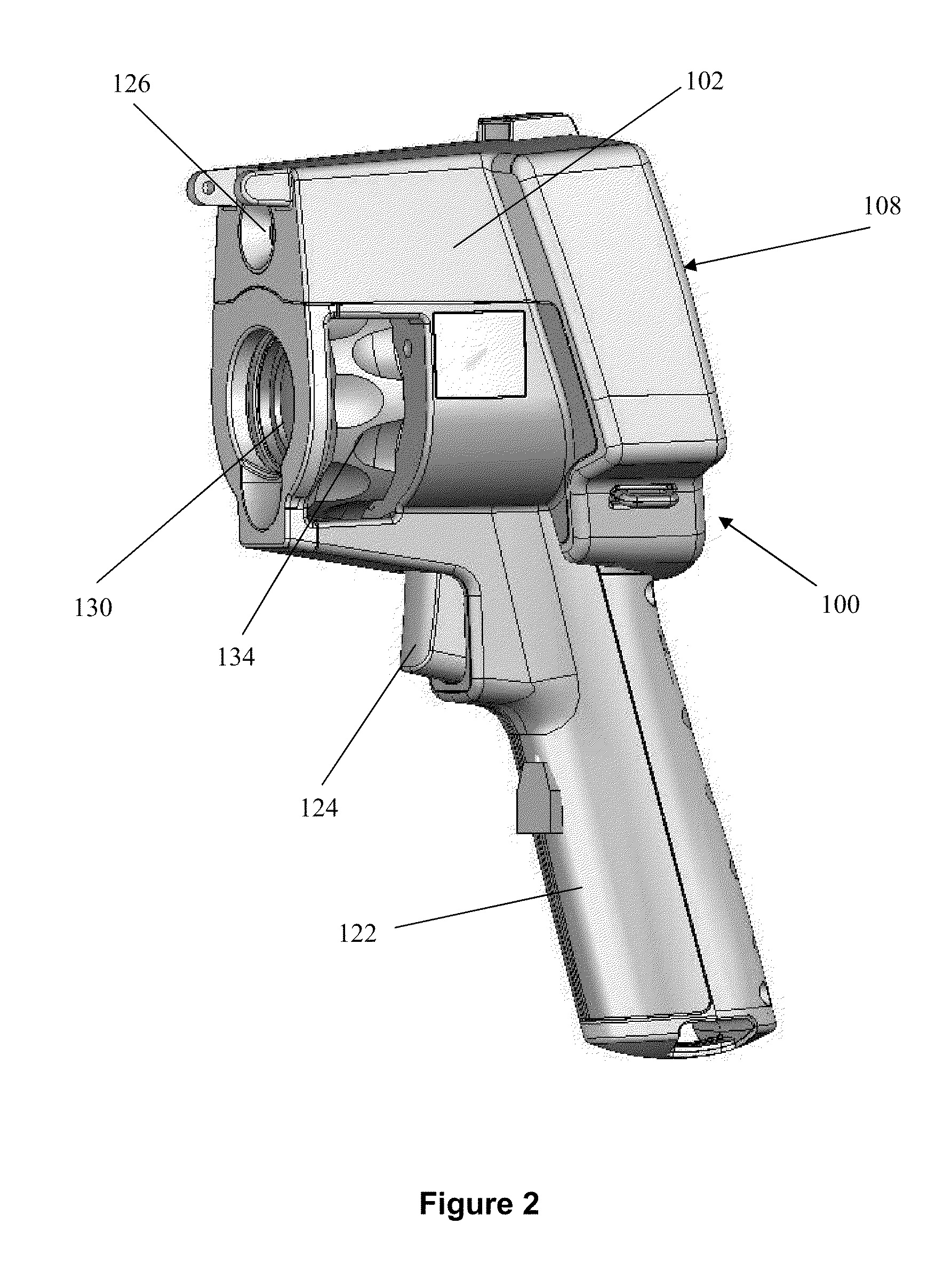
[0022]Embodiments of the present invention relate to an infrared (IR) camera with a lens position sensor. In some embodiments, the camera includes imaging capabilities, such as thermal imaging capabilities where the camera includes a thermal sensor that senses thermal or infrared radiation from a target scene. The thermal sensor may comprise an array of infrared detectors, such as a focal plane array (FPA) that sense a thermal image of the target scene. In some such camera embodiments, the IR camera includes a display for viewing the sensed thermal imagery. Moreover, in some such camera embodiments, the IR camera may include a storage mechanism such that the instrument functions as an infrared (IR) c...


PUM


Abstract

A lens position sensor for infrared or other types of cameras, which is particularly useful in lens assemblies that have relatively limited axial travel between near field and far field lens focus positions. The camera includes a magnet or other stimulator coupled to a rotatable lens that extends within a magnet plane where the magnet plane is not normal to the optical axis of the lens. A magnetic or other sensor senses the position of the magnet, which is indicative of the lens position.

Description

TECHNICAL FIELD[0001]The present disclosure pertains to lens position sensors for infrared cameras or other types of cameras.BACKGROUND[0002]Handheld thermal imaging cameras, for example, including microbolometer detectors to generate infrared images, are used in a variety of applications, which include the inspection of buildings and industrial equipment. Many state-of-the-art thermal imaging cameras have a relatively large amount of built-in functionality allowing a user to select a display from among a host of display options, so that the user may maximize his ‘real time’, or on site, comprehension of the thermal information collected by the camera.[0003]As is known, infrared cameras generally employ a lens assembly working with a corresponding infrared focal plane array (FPA) to provide an image of a view in a particular axis. The operation of such cameras is generally as follows. Infrared energy is accepted via infrared optics, including the lens assembly, and directed onto the...

Claims


Application Information

Patent Timeline
IPC IPC(8): G02F1/01G02B7/04
CPCH04N5/2254G02B7/10H04N23/55
Inventor JOHNSON, KIRK R.SHEARD, JUSTIN M.
Owner JOHN FLUKE MFG CO INC
Why Eureka
Try Eureka