Method and arrangement for fully automatic function checking of internal combustion engines

a technology of internal combustion engines and function checks, applied in the directions of vehicular safety arrangements, pedestrian/occupant safety arrangements, transportation and packaging, etc., can solve the problem that the solution often cannot be implemented

Inactive Publication Date: 2010-10-28
AUDI AG
View PDF45 Cites 6 Cited by
  • Summary
  • Abstract
  • Description
  • Claims
  • Application Information

AI Technical Summary

Benefits of technology

[0006]The object is achieved in that a guide device is arranged on the bonnet, in that an element of the lock that consists of locking hooks and clips is in engagement with the guide device, and in that in the closed and locked bonnet, the latter can be moved via the guide device relative to the locking hook and the clip. As a result, the clip or the locking hook can be of conventional design. They only have to be provided with a sliding means, so that they are displaceable in the longitudinal direction on the guide device which is arranged on the bonnet. A great advantage of this arrangement consists in the fact that the locking position always remains the same independently of the displacement direction and the displacement position. The angular positions between the locking hook and the clip are not changed. When the bonnet is displaced backward, there is no collision between the locking hook or the clip / pin and the engine package. Nevertheless, the locking device can be activated in the customary way. It is thus easily possible to move the locking hook out from the second locking stage by pressing a rocker. Overall, a very compact system is achieved, which can be installed in the center and integral with the bonnet. Advantageously, the actuating element of the active hinge system that is present is used to move the bonnet backward even in the locking area.

Problems solved by technology

Such a solution often cannot be implemented because of the structural conditions, since in the displacement of the bonnet, the parts of the locking device would collide with engine components that are arranged relatively high.

Method used


Image

  • Method and arrangement for fully automatic function checking of internal combustion engines
  • Method and arrangement for fully automatic function checking of internal combustion engines
  • Method and arrangement for fully automatic function checking of internal combustion engines

Examples


Embodiment Construction

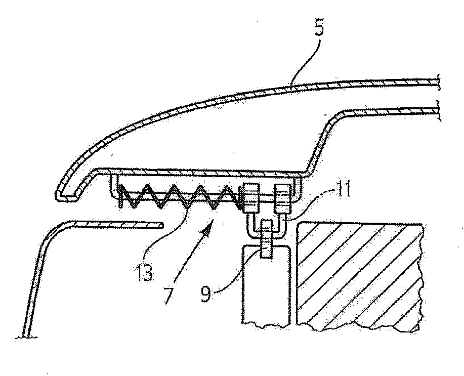
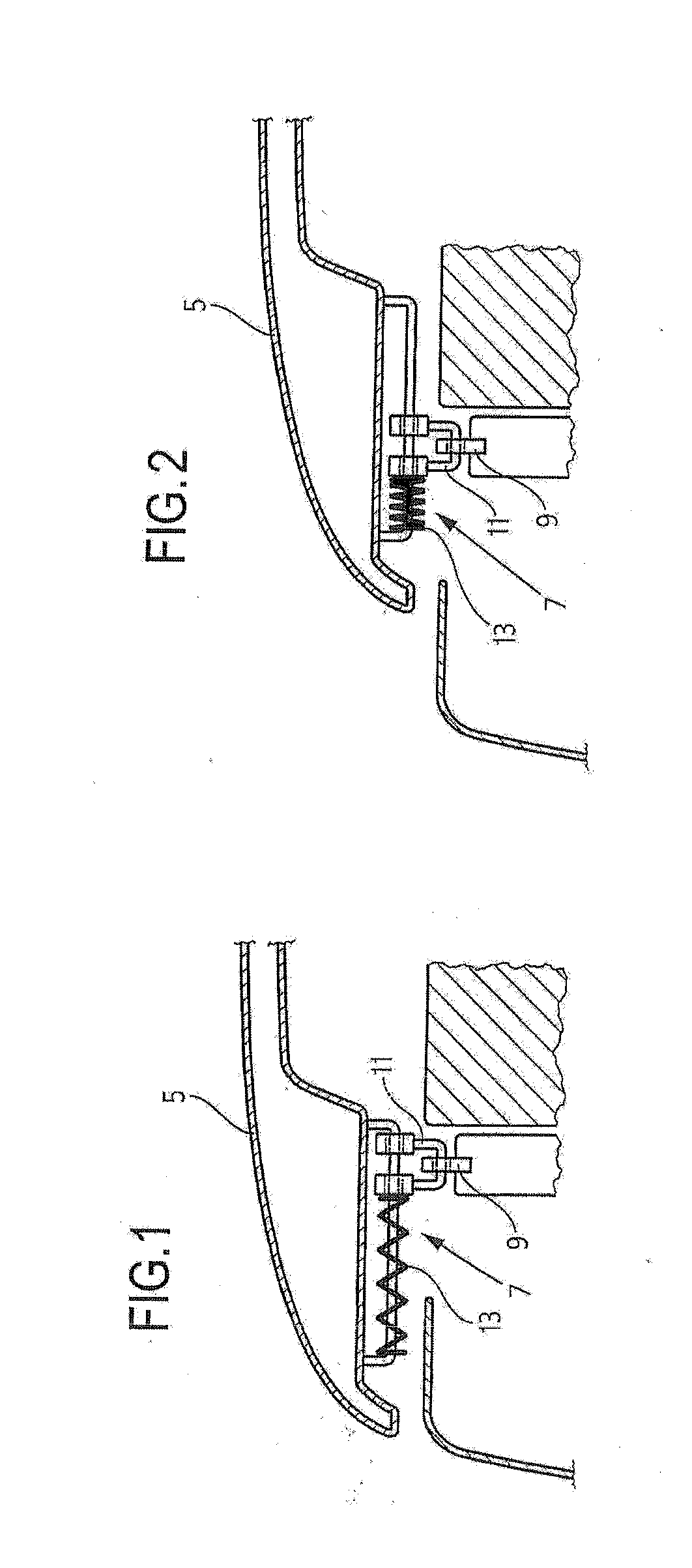
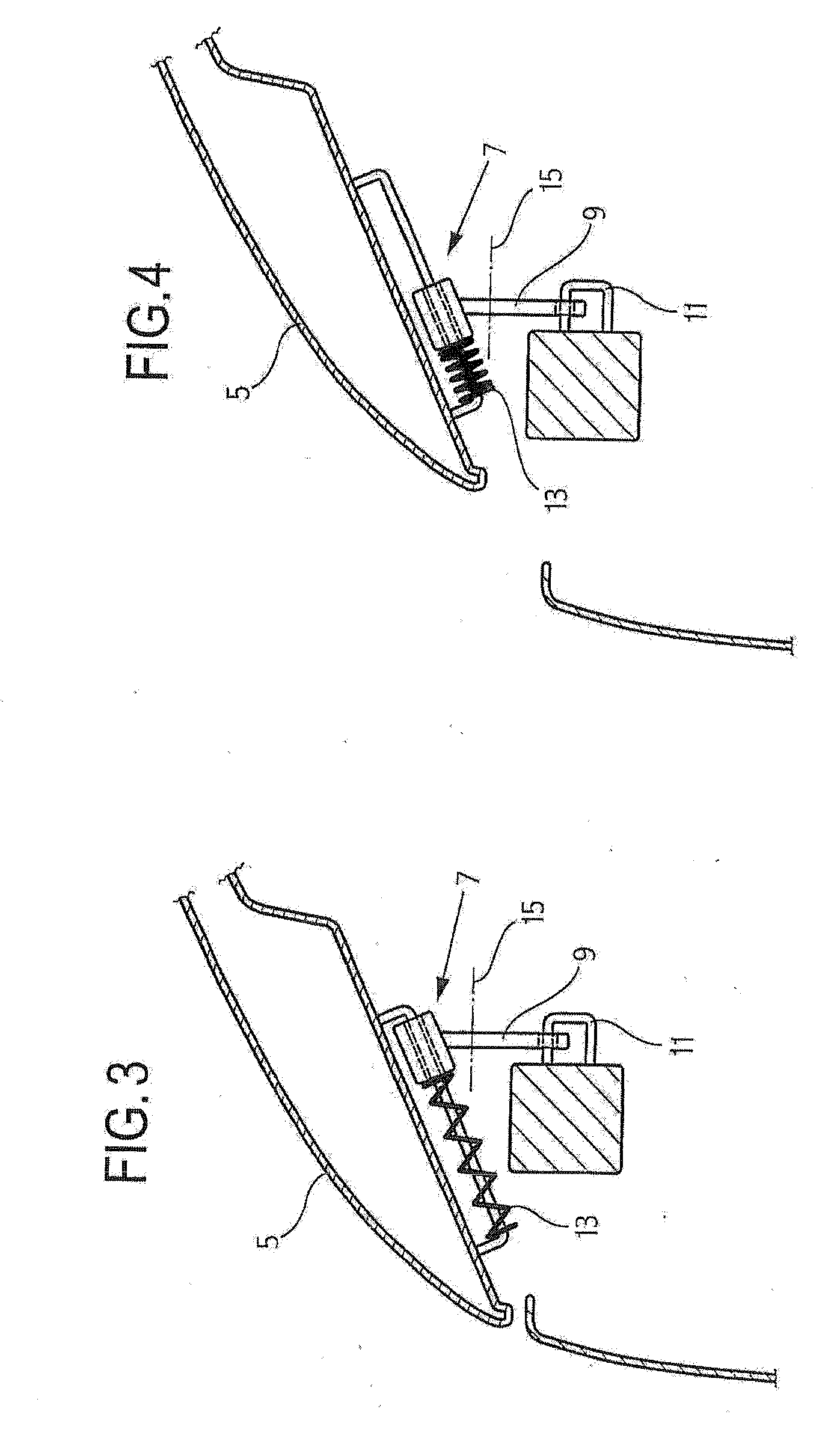
[0017]All depictions according to FIGS. Ito 4 show the front section of a bonnet 5, a guide device 7 that is arranged in the front end area thereof, and a locking device, which comprises a locking hook 9 and a clip 11 as essential components. In addition, other adjoining components, which are not referenced, specifically, a front body edge, a part of a front end, and the engine package, are shown.

[0018]FIGS. 1 and 2 show a first embodiment, FIG. 1 depicting the starting position, i.e., the normal operating state, and FIG. 2 showing the conditions in the bonnet 5 that is displaced backward. According to this embodiment, the clip 11 is arranged in the guide device 7, so that it passes from the position shown in FIG. 1 to the position according to FIG. 2 when the bonnet is displaced backward. In addition to the frictional forces in the guide, only the force of a compression spring 13 counteracts this movement. During the entire displacement travel, the relationship between the locking ...


PUM


Abstract

In a locking device for the bonnet of a motor vehicle, a guide device is arranged on the bonnet, whereby an element of the lock that consists of the locking hook and clip is in engagement with the guide device, and whereby when the bonnet is closed and locked, the latter can be displaced relative to the locking hook and the clip via the guide device.

Description

BACKGROUND OF THE INVENTION[0001]Known locking devices for the bonnet are in most cases arranged in the center and have a catch system with two locking stages. The second locking stage is used to prevent accidental opening of the bonnet in the event the first locking stage fails. The second locking stage is also used when the bonnet is unlocked from the passenger compartment and release of the second locking stage occurs from outside by a rocking activation.[0002]The known locking devices are usually designed so that a locking hook engages behind a pin or a clip. To improve pedestrian protection in active bonnet systems, i.e., those systems in which the bonnet is moved backward to lift the leading edge of the bonnet, the pin or the clip would have to be made very long for the locking hook to always be engaged. Such a solution often cannot be implemented because of the structural conditions, since in the displacement of the bonnet, the parts of the locking device would collide with e...

Claims


Application Information

Patent Timeline
Patent Type & Authority Applications(United States)
IPC IPC(8): E05C19/10E05C19/00B60R21/34B60R21/38
CPCE05B77/08B60R21/38Y10T292/08Y10T292/0911Y10T292/0926
Inventor ROTH, DIPL.-ING. FRANZBAUMHOF, KARSTENBURGSTAHLER, OLIVERDIX, NORMAN
Owner AUDI AG
Why Eureka
Try Eureka