
Automatic system information determination of distributed renewable energy systems

a distributed renewable energy and information determination technology, applied in nuclear engineering, electric devices, nuclear elements, etc., can solve the problems of increasing difficulty in uniformly gathering data, increasing importance and difficulty in gathering data about the characteristics of all the systems, and less well known long-term efficiency and durability

Active Publication Date: 2010-10-28
LOCUS ENERGY
View PDF0 Cites 32 Cited by
  • Summary
  • Abstract
  • Description
  • Claims
  • Application Information

AI Technical Summary

Benefits of technology

[0003]As the field of renewable power / renewable energy systems grows, monitoring the performance and output of these systems on an ongoing basis becomes more important for the following reasons: 1) it helps quantify to the system owner the exact benefits of the system and validates its economic payback; 2) it informs the system owner or service provider of issues so that they can be resolved quickly, reducing wasted generation capacity; and 3) it provides data which over time can be used to improve renewable energy system design and performance.
[0006]Even if data has been gathered manually, there is often a problem of human error either at the point of data gathering or at the point of communicating that data and entering into it a computerized system. Having an automated way to check this data is important to improve the data quality.
[0009]As can be seen, there are many reasons why users might want to be able to identify system information from a stream of monitored performance data (e.g. kilowatt hours, kilowatts, BTUs, etc.). For example, when one is monitoring a large number of distributed renewable energy systems it may not be feasible to have the people who are attaching monitoring equipment to different pieces of electrical equipment record data about the equipment that they are attaching the monitors to. In order to make use of the monitoring data, however, it is often necessary to understand what it is that is being monitored. Being able to automatically determine these parameters would significantly reduce the man-hours required to set up monitoring systems, and could also reduce user input errors. Similarly, being able to automatically determine system configuration parameters would allow one to validate the parameters that someone may have entered manually.

Problems solved by technology

These are encased in glass and are extremely durable, though expensive.
While these technologies are much less expensive and will greatly aid in the spread and adoption of solar power, their long-term efficiency and durability are less well known.
As the number of discrete renewable energy systems grows, gathering data about the characteristics of all the systems becomes increasingly important and more challenging to do.
Gathering this data becomes increasingly challenging to do in a uniform way, because often the individuals installing the system do not have a strong incentive to make precise measurements across a wide range of possible variables (e.g., because their objective is to install the system quickly, reducing installation cost).
Additionally, individuals may want information that was not considered an important data point to be gathered when the system was originally installed.
Even if data has been gathered manually, there is often a problem of human error either at the point of data gathering or at the point of communicating that data and entering into it a computerized system.
For example, when one is monitoring a large number of distributed renewable energy systems it may not be feasible to have the people who are attaching monitoring equipment to different pieces of electrical equipment record data about the equipment that they are attaching the monitors to.

Method used


Image

  • Automatic system information determination of distributed renewable energy systems
  • Automatic system information determination of distributed renewable energy systems
  • Automatic system information determination of distributed renewable energy systems

Examples


Embodiment Construction

[0031]The following detailed description is of the best currently contemplated modes of carrying out the invention. The description is not to be taken in a limiting sense, but is made merely for the purpose of illustrating the general principles of the invention, since the scope of the invention is best defined by the appended claims.

[0032]The present invention provides systems and methods that reduce and / or eliminate the need for user input about system configuration of monitored electrical systems (such as renewable power systems) by determining the input through comparative diagnostics. The quality of data is improved over direct input by users, or augments direct input by users, providing additional data about system configuration of monitored electrical systems based upon their consumption and / or output and known environmental conditions.

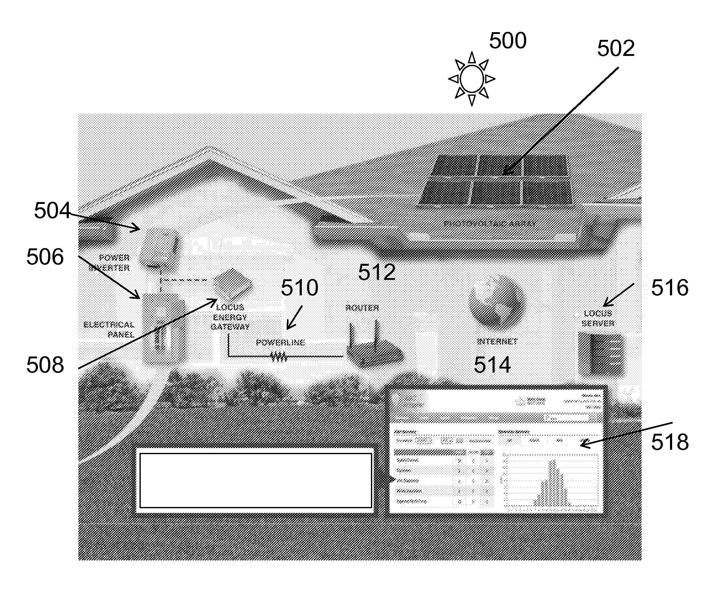
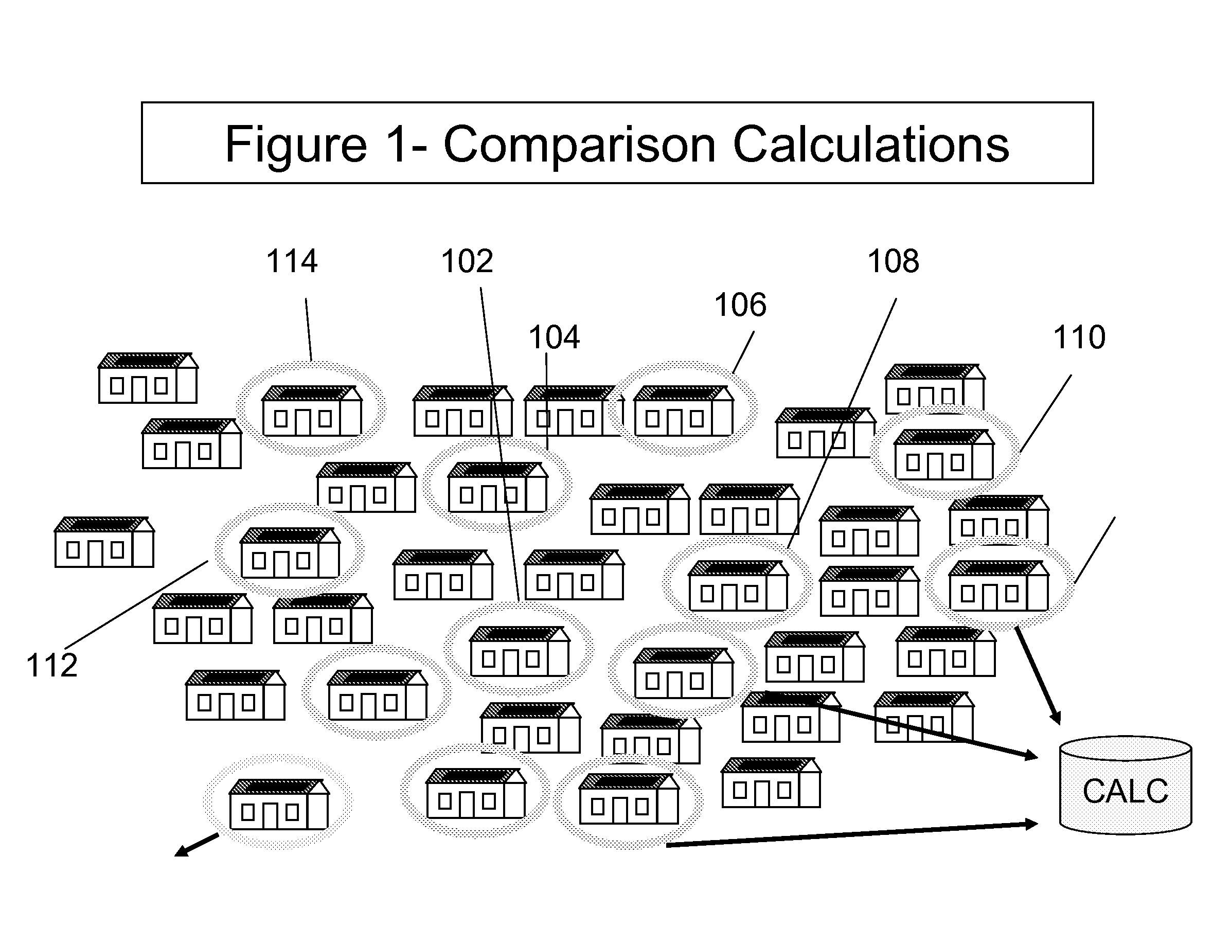
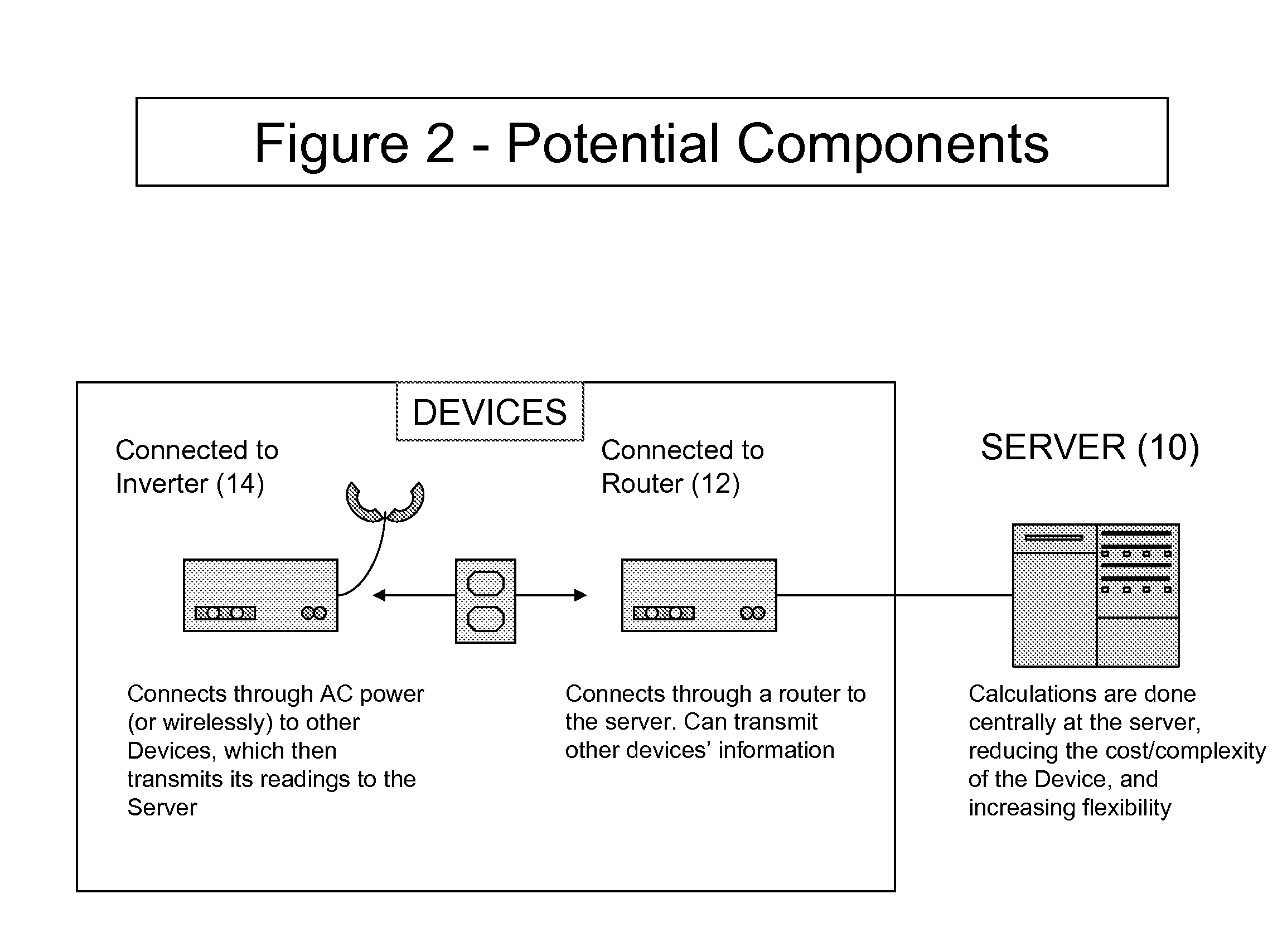
[0033]FIGS. 1-5 provide examples of a monitored electrical system (in this case a renewable power system and more specifically a photovoltaic ...


PUM


Abstract

A computer processor implemented method of determining system configuration information of a monitored electrical system without the need for user input by constructing a data set of a standard performance curve for at least one system type; defining at least one characteristic feature for each system type; determining the required data to identify at least one system type according to at least one of the standard performance curve and characteristic feature; remotely acquiring the required data; comparing system acquired electrical system data to at least one system type and correlated standard performance curves and correlated characteristic features to provide system configuration information for at least one monitored electrical system to provide the specific type of monitored electrical system.

Description

[0001]This application claims priority to application Ser. No. 11 / 949,035 filed Dec. 2, 2007 entitled “Systems and Methods for Monitoring and Diagnosing the Power Generated by Renewable Power Systems” and application Ser. No. 11 / 673,649 Feb. 12, 2007 entitled “Systems and Methods for Providing Renewable Power Systems by Aggregate Cost and Usage.” Each of which are incorporated herein by reference.[0002]The present invention relates to systems and methods for automatic determination of system information related to distributed renewable energy systems.[0003]As the field of renewable power / renewable energy systems grows, monitoring the performance and output of these systems on an ongoing basis becomes more important for the following reasons: 1) it helps quantify to the system owner the exact benefits of the system and validates its economic payback; 2) it informs the system owner or service provider of issues so that they can be resolved quickly, reducing wasted generation capacity;...

Claims


Application Information

Patent Timeline
IPC IPC(8): G08B21/00G06F19/00G01R21/00
CPCG06Q10/04G06Q10/06H02J3/383H02J3/386H02J13/0062Y04S10/123Y02E40/72Y04S40/124Y02E10/563Y02E10/763Y02E60/7838H02J3/382Y04S10/60H02J2300/28H02J2300/22H02J2300/20H02J2300/24H02J3/381H02J13/00016Y02E10/56Y02E10/76Y02E40/70Y02E60/00Y04S10/50
Inventor KERRIGAN, SHAWNHERZIG, MICHARL
Owner LOCUS ENERGY
Learn More