Compact snapshot polarimetry camera

a polarimetry and camera technology, applied in the field of compact snapshot polarimetry camera, can solve the problems of increasing the risk of breakage, adding mechanical noise, and adding complexity to the instrumen

Inactive Publication Date: 2010-10-28
THE ARIZONA BOARD OF REGENTS ON BEHALF OF THE UNIV OF ARIZONA
View PDF14 Cites 28 Cited by
  • Summary
  • Abstract
  • Description
  • Claims
  • Application Information

AI Technical Summary

Benefits of technology

[0010]In one embodiment, the analyzer is arranged such that a transmission axis of the analyzer is not coincident with the direction of an optical axis of the second polarization-sensitive beam-splitter optic. In one embodiment, a polarization-sensitive beam-splitter optic is a Savart plate. In one embodiment, both first and second polarization-sensitive beam-splitter optics are Savart plates. In one embodiment, the analyzer is arranged such that a transmission axis of the analyzer is arranged at an angle of 45° with respect to the direction of an optical axis of the second polarization-sensitive beam-splitter optic. In one embodiment, the retarder is a half-wave plate. In one embodiment, the optics unit further comprises a focusing lens. In one embodiment, the optics unit further comprises an imaging lens. In one embodiment, a detector is positioned at the focal point (or image plane) of the focusing (or imaging) lens. In one embodiment, a Fourier transform lens is placed at or about the focal point or focal plane of the focusing lens. In one embodiment, the optics unit further comprises a detector or image sensor. In one embodiment, the detector is a CCD. In one embodiment, the detector is CMOS. In one embodiment the detector is a camera. In one embodiment, the detector is a miniature camera. In one embodiment, the detector is a cell-phone camera. In one embodiment, the optics unit is less than 1.5 cm long. It is known that the Fourier transform can be taken optically, instead of post-processing the captured image in software. Optical Fourier transformation embodiments are included in the disclosure herein, and the description herein can be modified to take into account these embodiments without undue experimentation.
[0011]Also provided is a polarimetry camera comprising: a first Savart plate; a half-wave plate; a second Savart plate; an analyzer; a lens; and an image sensor, through which input light passes in sequence along an optical axis, wherein the half-wave plate is positioned so that an optical axis of the half-wave plate forms an angle of 22.5° with respect to the direction of the optical axis of the first Savart plate, an optical axis of the first and second Savart plates are substantially the same, and the transmission axis of the analyzer forms an angle of 45° with an optical axis of the second Savart plate. The image sensor can be a camera. The image sensor can be a display. The image sensor can be a conventional detector, such as a CCD or CMOS. In an embodiment, the half-wave plate is optional, as long as light passing through the polarization-sensitive beam splitters is sheared to interfere at the image plane.

Problems solved by technology

Rotating and moving parts require additional control systems, add complexity to the instrument, add mechanical noise and increases risk of breakage.
In addition, a rotational or motional scheme requires several measurements to be taken to acquire state of polarization information from the object, limiting measurements to static scenes and slowing frame rates for video acquisition.
These systems have additional complexity, lower resolution, higher cost and other disadvantages.

Method used


Image

  • Compact snapshot polarimetry camera
  • Compact snapshot polarimetry camera
  • Compact snapshot polarimetry camera

Examples


example 1

Simulation

[0042]To simulate the system, the above mentioned parameters were inserted into Zemax ray tracing software (see zemax.com) with a 5 mm diameter aperture. The image spot diagrams and ray shearing diagrams from this simulation can be seen in FIG. 6. Two different field points were sampled and the object was 1 m distant. The image quality looks impressive for both the on-axis and off-axis field points, with the aberrated spot size close to the diffraction limit. This result shows the SPs do not introduce excessive aberrations when imaging a finite conjugate object. In FIG. 6(b), the on-axis ray shearing diagrams are consistent with expectation, i.e., four rays are sheared equally and diagonally with values of √{square root over (2)}Δ=113 μm. Conversely in the off-axis case, however, the four rays are not sheared ideally and their shearing distances are not equal to each other. Both issues are due to the asymmetry of the SP itself. This deviation worsens form on-axis to off-ax...

example 2

Camera-Scale System

[0043]A system with commercially available elements, all of which were one-inch in diameter and mounted independently was built. The SPs were manufactured by Karl Lambrecht Inc. A 75 mm focal-length lens was used, extending the total length by a factor of 15 from the imaging system. This parameter can be changed, as known in the art. A photo of the actual polarimeter built is shown in FIG. 5.

[0044]FIG. 7(a) shows a raw image obtained by the polarimetry camera and FIG. 7(b) shows the reconstructed Stokes images. A uniform polarized image was formed with a linear polarizer at 22.5° (S1=0.707, S2=0.707, S3=0) was used as a reference to calibrate the system. The camera's viewing angle was about 60 degrees with respect to the ground and the object, a car, was about 30 m away. In FIG. 7(a), the clear fringes seen across the image indicates the existence of polarization signals. This is due to the skewed sun-object-camera angle and less scattering surfaces that are insid...

example 3

Miniature System

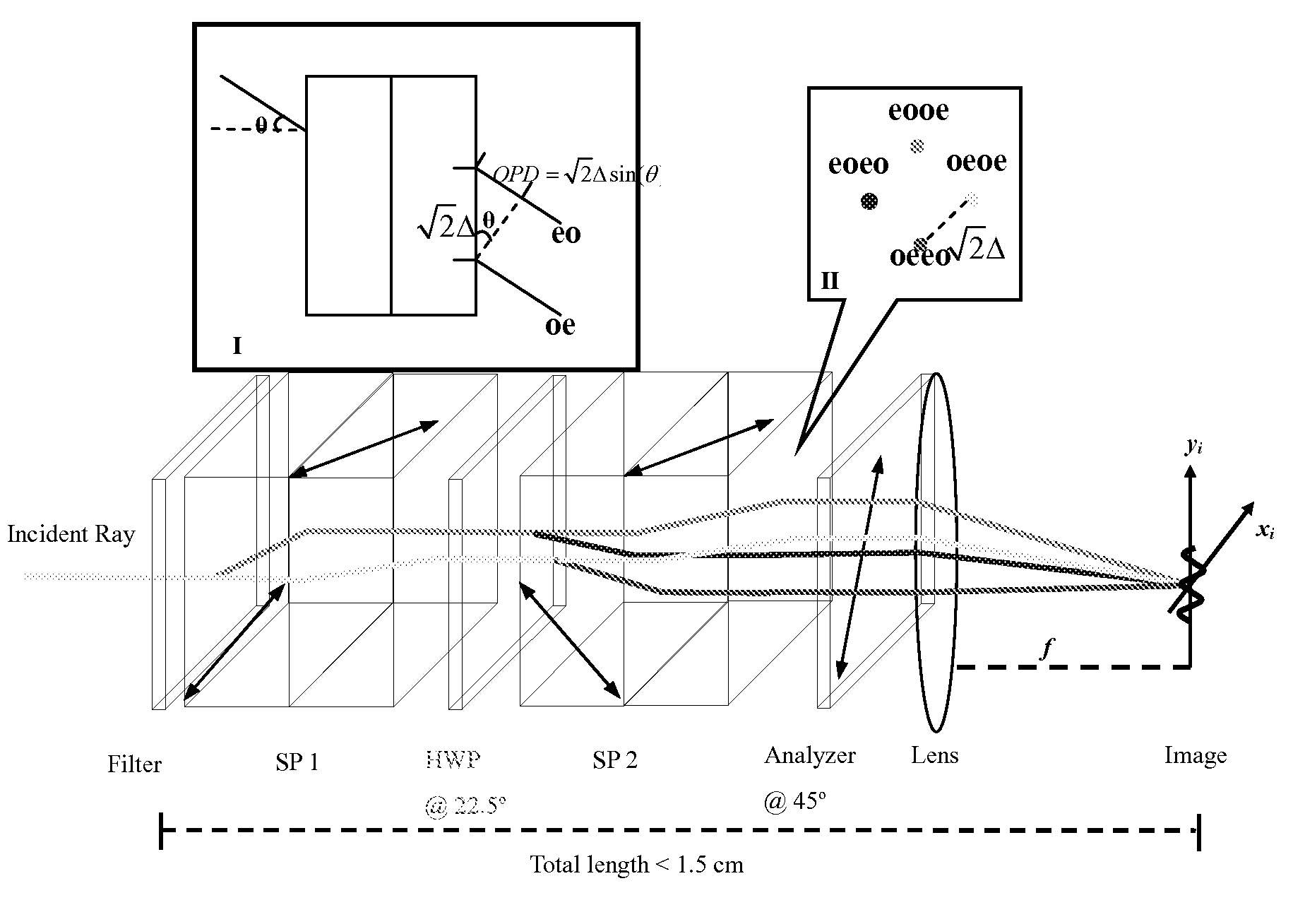
[0045]Following the theory and teachings herein, a miniaturized system can be built. A miniature system can modify a cell phone camera with f=5 mm and pixel spacing 4.75 μm, λ=0.55 μm, and Ω=4 pixels / fringe. The required thickness t then equals 1.54 mm and the total length of the polarimeter is shorter than 1.5 cm. The elements can be glued together using appropriate glue and simply placed or glued in front of a miniature camera such as a cell phone camera.

[0046]Other size systems can be made using the teachings described herein. The systems include the necessary optics and light guiding as required for a given application. For example, all systems may include a computer having the necessary program for the analysis of the waveforms.


PUM


Abstract

An imaging polarimeter optics unit comprising: a first polarization-sensitive beam-splitter optic, a retarder, a second polarization-sensitive beam-splitter optic, and an analyzer, through which input light passes in sequence, wherein the retarder and polarization-sensitive beam-splitters cause the input light to have optical components that provide different information about the state of polarization of the input beam is provided.

Description

CROSS-REFERENCE TO RELATED APPLICATIONS[0001]This application takes priority from U.S. provisional application Ser. No. 60 / 923,129, filed Apr. 12, 2007, and U.S. provisional application Ser. No. 61 / 063,561, filed Feb. 4, 2008, the disclosures of which are hereby incorporated by reference to the extent not inconsistent with the disclosure herein.REFERENCE TO FEDERAL FUNDING SUPPORT[0002]This invention was made with government support under Grant Number R21 EY015499 awarded by NIH. The government has certain rights in the invention.BACKGROUND OF THE INVENTION[0003]Electromagnetic radiation contains intensity, color (wavelength), and polarization information. The human eye and conventional cameras are not polarization sensitive. The polarization parameters of light are orthogonal to the direction of propagation of the light. The state of polarization (“SOP”) from an image is determined from the four Stokes vectors. As the light interacts with objects in the environment, the polarizatio...

Claims


Application Information

Patent Timeline
Patent Type & Authority Applications(United States)
IPC IPC(8): G01J4/04H04N7/18
CPCG01J4/04G03B15/00G03B11/00
Inventor SCHWIEGERLING, JAMES T.DERENIAK, EUSTACEKUDENOV, MICHAEL W.LUO, HAITAOOKA, KAZUHIKODEHOOG, EDWARD A.
Owner THE ARIZONA BOARD OF REGENTS ON BEHALF OF THE UNIV OF ARIZONA
Why Eureka
Try Eureka