
Channel Estimation Techniques for OFDM

a channel estimation and channel estimation technology, applied in orthogonal multiplexing, multiplex communication, baseband system details, etc., can solve the problems of moderate to high complexity and performance of transform domain methods, moderate complexity and high performance, and truly two-dimensional, so as to achieve large buffer requirements and delay effect large

Active Publication Date: 2010-10-28
HONG KONG APPLIED SCI & TECH RES INST
View PDF7 Cites 23 Cited by
  • Summary
  • Abstract
  • Description
  • Claims
  • Application Information

AI Technical Summary

Benefits of technology

The invention provides a system, method, and computer program product for efficient estimation of channel frequency responses in OFDM applications. The invention uses a weighted summation approach to estimate the channel response at data subcarriers by using pre-calculated weight matrices based on the known channel response at pilot locations. The weight matrices are pre-calculated for a set of well-defined channel profiles and are used in a competition algorithm to determine the best weight vector for each window. The use of pre-calculated weight matrices reduces complexity and cost compared to other techniques. The invention can be applied to both 1-D and 2-D methods, and the order in analyzing time and frequency domains can affect the performance of the 2-D method. The weight vector with the highest MSE (maximum signal-to-noise ratio) is used to estimate the channel response for each OFDM symbol. The invention can be used in various systems, such as communication systems and radar systems.

Problems solved by technology

The transform domain method has a moderate to high complexity and performance.
Yet another technique is the Minimum Mean Square Error (MMSE) method, which typically uses channel statistic information and has moderate complexity and high performance.
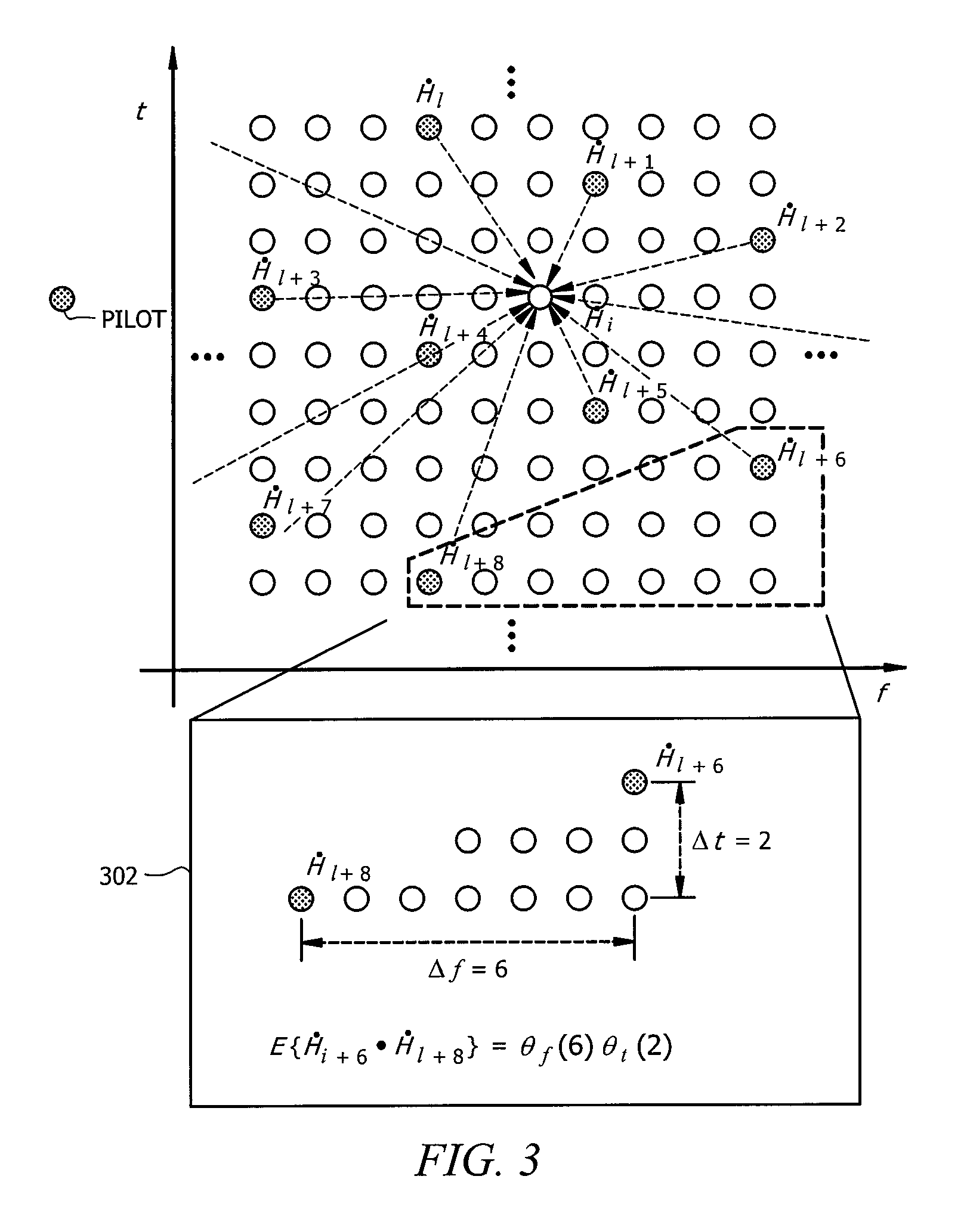
Some MMSE methods use both a 1-D time domain estimation and a 1-D frequency domain estimation (also called a sequential 1-D method) but are not truly two-dimensional (2-D) because pilots with different frequency and time indices from the data subcarrier being estimated are not able to be used in the estimation.
Currently available MMSE methods fail to strike an adequate balance between efficiency and accuracy by performing needless recalculating and / or performing estimation using more pilots than is necessary.

Method used


Image

  • Channel Estimation Techniques for OFDM
  • Channel Estimation Techniques for OFDM
  • Channel Estimation Techniques for OFDM

Examples


Embodiment Construction

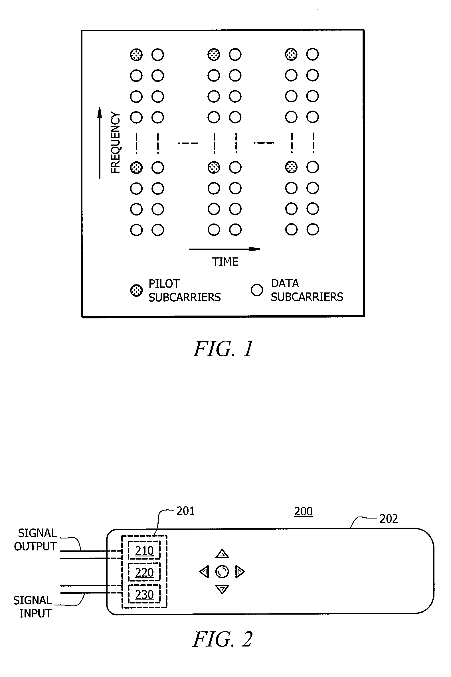
[0029]FIG. 2 is an illustration of exemplary system 200 adapted according to one embodiment of the invention. System 200 includes OFDM receiver 201, which in this embodiment is part of digital television receiver 202. OFDM receiver 201 is not limited to use in television receivers, as other uses are also possible, such as within handheld devices (e.g., cellular phones, Personal Digital Assistants, laptop / desktop computers, and the like).

[0030]OFDM receiver 201 receives a signal that includes subcarriers spread across the time and frequency domains. Channel estimator 210 processes the signal and produces channel frequency response estimates therefrom, as described in more detail below. Demodulator 220 uses the channel frequency responses to perform coherent demodulation of the data tones. Demodulator 220 utilizes the received frequency data tones and the frequency channel response to recover the transmitted data symbols (for example, BPSK, QPSK, QAM symbols). The recovered data symbo...


PUM


Abstract

An Orthogonal Frequency Division Multiplexing (OFDM) receiver comprises: a channel estimator receiving a signal that includes a plurality of symbols, each of the symbols including a plurality of pilots and a plurality of data subcarriers, wherein each symbol further includes at least one pilot subcarrier, the estimator using a first channel response estimate of the at least one pilot subcarrier in a first symbol to select a first weight matrix from a plurality of pre-generated weight matrices, and generating channel estimation information for data subcarriers in the first symbol using the selected first weight matrix.

Description

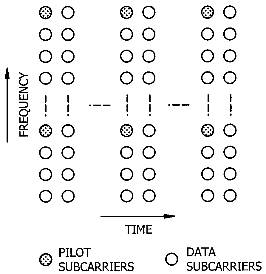
TECHNICAL FIELD[0001]The present description is related, generally, to Orthogonal Frequency Division Multiplexing (OFDM) systems and, more specifically, to OFDM receivers generating channel estimation information.BACKGROUND[0002]Orthogonal Frequency Division Multiplexing (OFDM) systems transmit multiple subcarriers at the same time using a multitude of frequencies. An example OFDM signal is shown in FIG. 1, including data subcarriers and pilot subcarriers. FIG. 1 shows a frequency axis and a time axis, and the subcarriers (both pilot and data subcarriers) with the same time index together make up a symbol.[0003]When an OFDM signal is transmitted and then received by a receiver, the received signal is somewhat different from the transmitted signal, as shown in Equation 1, where y(t,k) is the received subcarrier symbol, x(t,k) is the transmitted subcarrier symbol, H(t,k) is the channel frequency response of the subcarrier symbol, and n(t,k) is noise. The channel frequency response is ...

Claims


Application Information

Patent Timeline
Patent Type & Authority Applications(United States)
IPC IPC(8): H04K1/10
CPCH04L25/022H04L27/2647H04L25/025H04L25/0232
Inventor ZHENGANG, PANKWAN, MAN W.ZHOU, YIQINGLI, TAO
Owner HONG KONG APPLIED SCI & TECH RES INST
Learn More