
Expandable intramedullary nail for small bone fixation

a small bone and intramedullary technology, applied in the field of small bone fixation devices and methods, can solve the problems of difficult traditional fixation healing procedures such as splinting and casting, and achieve the effect of improving frictional stability

Inactive Publication Date: 2010-10-28
GLOBERMAN OREN
View PDF103 Cites 7 Cited by
  • Summary
  • Abstract
  • Description
  • Claims
  • Application Information

AI Technical Summary

Benefits of technology

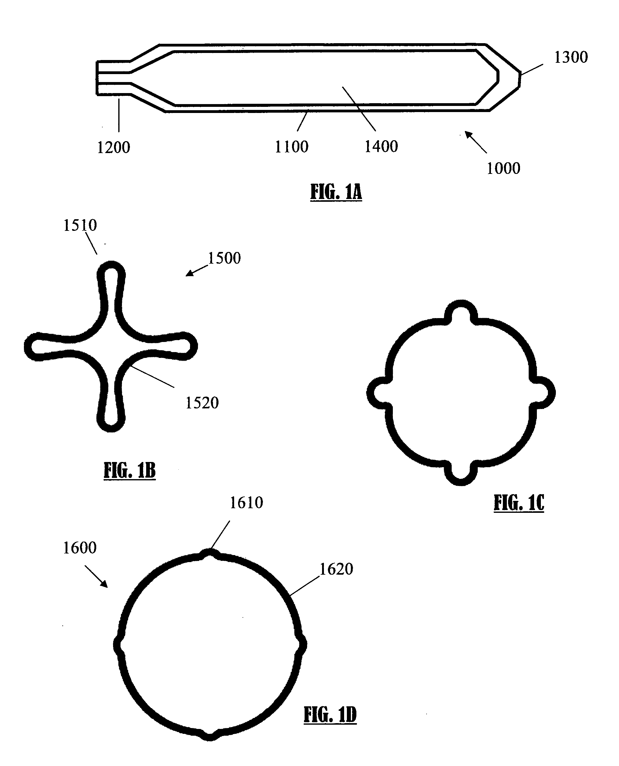
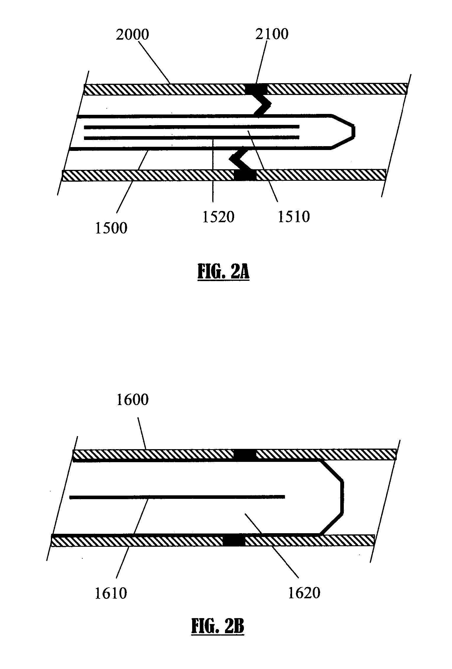
[0012]In an exemplary embodiment of the invention, the nail includes friction means for preventing slipping of the nail with respect of bone interface. Optionally, said friction means include but are not limited to: roughened textures, spikes and / or fins; said fins may extend longitudinally and / or circumferentially. In a preferred exemplary embodiment of the invention, said friction means are functional when the nail is in at least partial expanded formation. Preferably, said friction means improves rotational and / or longitudinal immobilization stability. In an exemplary embodiment of the invention, when the nail transforms from a first crimped formation to an expanded formation (e.g. by inflation), a residual crimped-like pattern remains; said residual pattern further improves immobilization stability. Optionally, friction means, such as spikes, fins or bars, are attached to the nail outer surface, as for example by welding or soldering.
[0037]In one embodiment of the invention, an inflatable nail is used for internally fixating a fractured medullar bone provided in a collapsed formation, the nail is produced by radially crimping a tubular body, said nail when is at least partially inflated, includes longitudinal wrinkles that improve rotational stability and / or friction of the nail within bone.
[0038]In an exemplary embodiment of the invention, the nail has a width and excludes longitudinal fastener bars, wherein said width provides enough strength to withstand deformable stresses applied when nail is implanted in an inflated form.
[0045]Optionally, the nail, when expanded from said collapsed formation, cannot regain an identical shape to its original tubular shape prior to crimping. Optionally, said expanded nail contains residual wrinkles. Optionally, said wrinkles improve frictional stability with respect to bone medullar canal inner surface.

Problems solved by technology

The size and location of these bones make it difficult to provide traditional fixations healing procedures such as splinting and casting.

Method used


Image

  • Expandable intramedullary nail for small bone fixation
  • Expandable intramedullary nail for small bone fixation
  • Expandable intramedullary nail for small bone fixation

Examples


Embodiment Construction

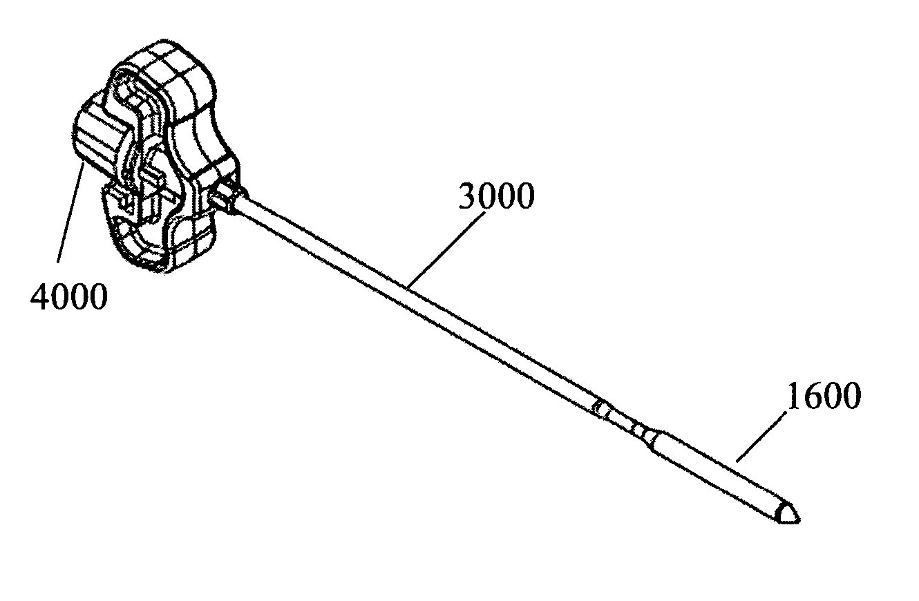
[0065]FIGS. 1A-1D schematically illustrate an expandable nail in accordance with an exemplary embodiment of the invention. FIG. 1A presents exemplary fixation nail 1000 in a maximal expanded formation. Nail 1000 includes hollow body 1100 that contains volume 1400, tip 1300 and inlet 1200. In an exemplary embodiment of the invention, body 1100 has a maximal outer diameter in the range of 2-10 mm, optionally 2.5 mm to 7 mm, optionally about 4.5 mm or optionally about 7 mm. Optional length of nail 1000 is 5 mm, optionally about 30 mm, optionally about 70 mm, optionally about 100 mm, optionally about 150 mm or lesser or higher or intermediate values.

[0066]In an exemplary embodiment of the invention, a nail having a length of 30-70 mm and maximal diameter of 4.5 mm in fully expanded form is especially intended for treating metacarpal or metatarsal fractures. In an exemplary embodiment of the invention, a nail having a length of about 100 mm and maximal diameter of about 6.8 mm in fully e...


PUM


Abstract

The present invention provides method and device for fixating a fractured bone by inflating an intramedullary nail using a manually operated nail inflation syringe. Optionally, the nail is provided attached to an insertion device that may also function as the inflation syringe. The two attached items are preferably provided as a single detachable element—sterile and ready for use.

Description

RELATED APPLICATIONS[0001]The present application claims the benefit under 119(e) of 60 / 917,125 filed May 10, 2007, the disclosure of which is incorporated herein by reference.FIELD OF THE INVENTION[0002]The present invention relates to devices and methods for fixating small bones.BACKGROUND OF THE INVENTION[0003]Fractures of small long bones, such as metacarpal, metatarsal bones, clavicle, ulna, radius and fibula, are very common. The size and location of these bones make it difficult to provide traditional fixations healing procedures such as splinting and casting. There is also a rising need to avoid invasive surgical procedures as requested when using fixating bolts, pins with or without combination with plates. A further need is the ability to prevent any relative movements or immobilizations of the bone fractures, including but not limited to lateral movements, rotation and torsion movements and bending movements.[0004]Newer less invasive techniques include boring of the metac...

Claims


Application Information

Patent Timeline
Patent Type & Authority Applications(United States)
IPC IPC(8): A61B17/58
CPCA61B17/7258A61B17/8872A61B17/8863A61B17/7291
Inventor BEYAR, MORDECHAYGLOBERMAN, OREN
Owner GLOBERMAN OREN
Learn More