Surgical instrument for the placement of ligature clips

a surgical instrument and ligature clip technology, applied in the field of surgical instruments for the placement of c-shaped ligature clips, can solve the problems of restricted arm pivot angle and insufficient space to accommodate ligature clips, and achieve the effect of reducing the size of the instrumen

Inactive Publication Date: 2010-10-28
AESCULAP AG
View PDF40 Cites 6 Cited by
  • Summary
  • Abstract
  • Description
  • Claims
  • Application Information

AI Technical Summary

Benefits of technology

[0018]It is particularly advantageous if the abutment surfaces are respectively arranged at the level of the corresponding arms, i.e. in the pivoting plane of these arms. In this case, “in the plane” means that the abutment surfaces do not run above or below the arms, thus the arms are not angled or bent in relation to their pivoting plane. This also assists i

Problems solved by technology

The arms that are located next to one another and can be pivoted relative to one another must move within a very narrow cross-section of a barrel-like instrument part, and this results in the pivoting angle of the arms being restricted

Method used


Image

  • Surgical instrument for the placement of ligature clips
  • Surgical instrument for the placement of ligature clips
  • Surgical instrument for the placement of ligature clips

Examples


Embodiment Construction

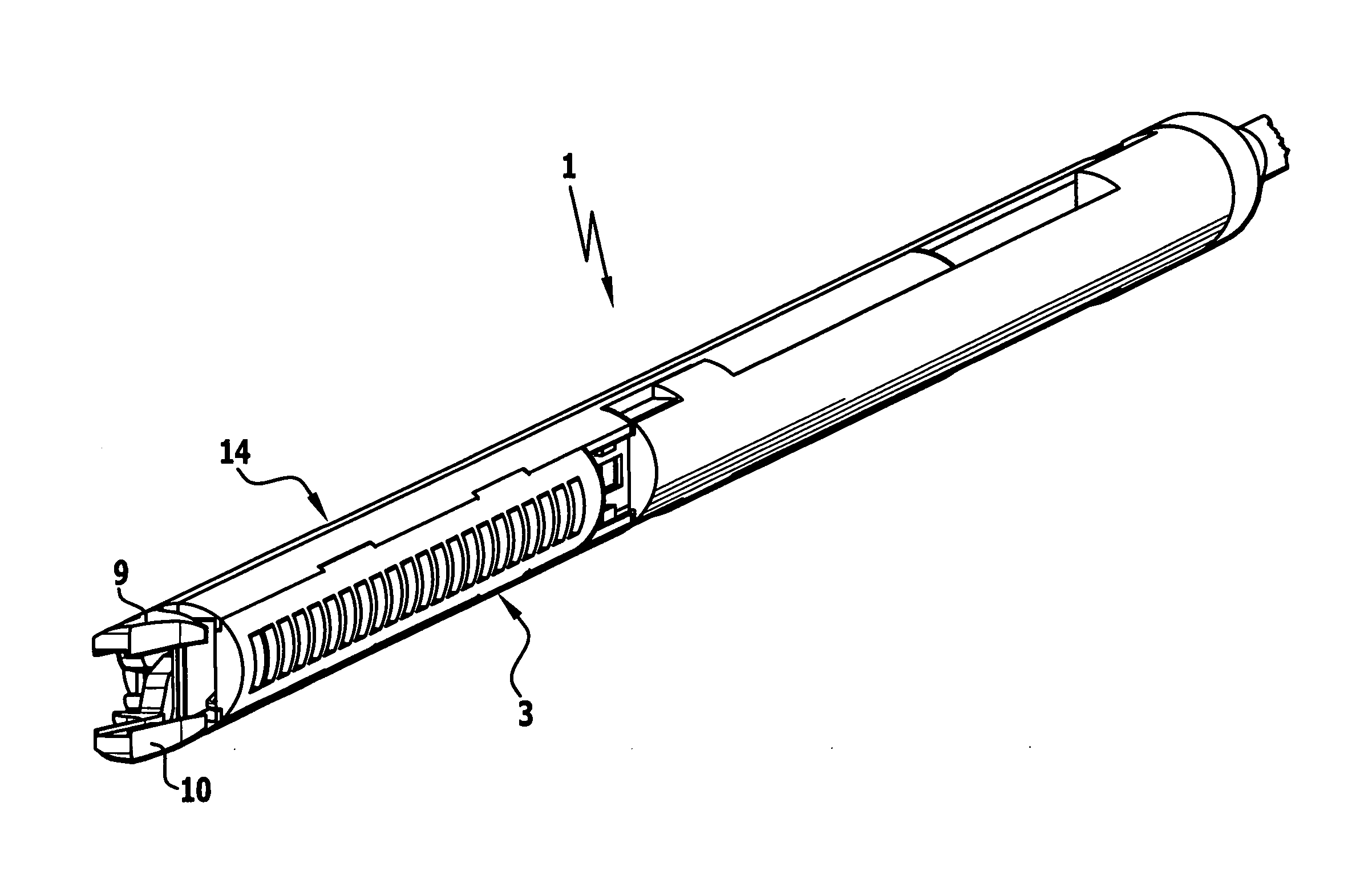
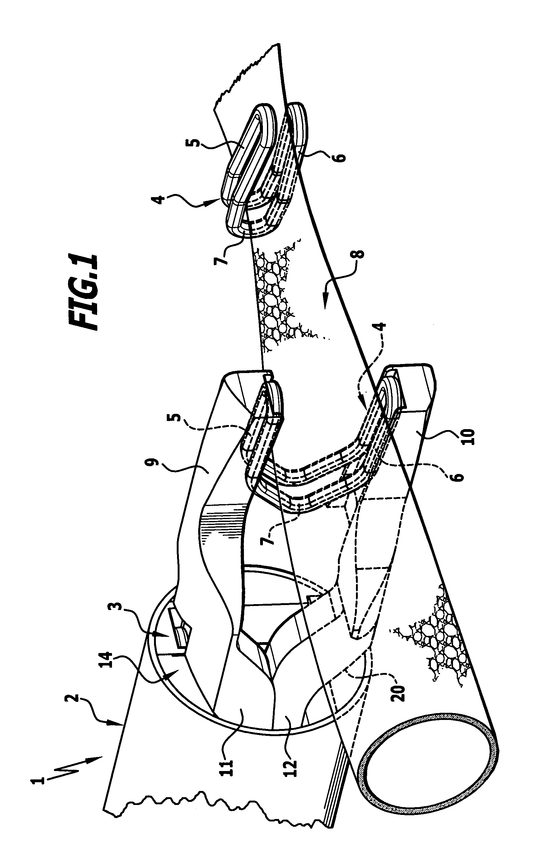
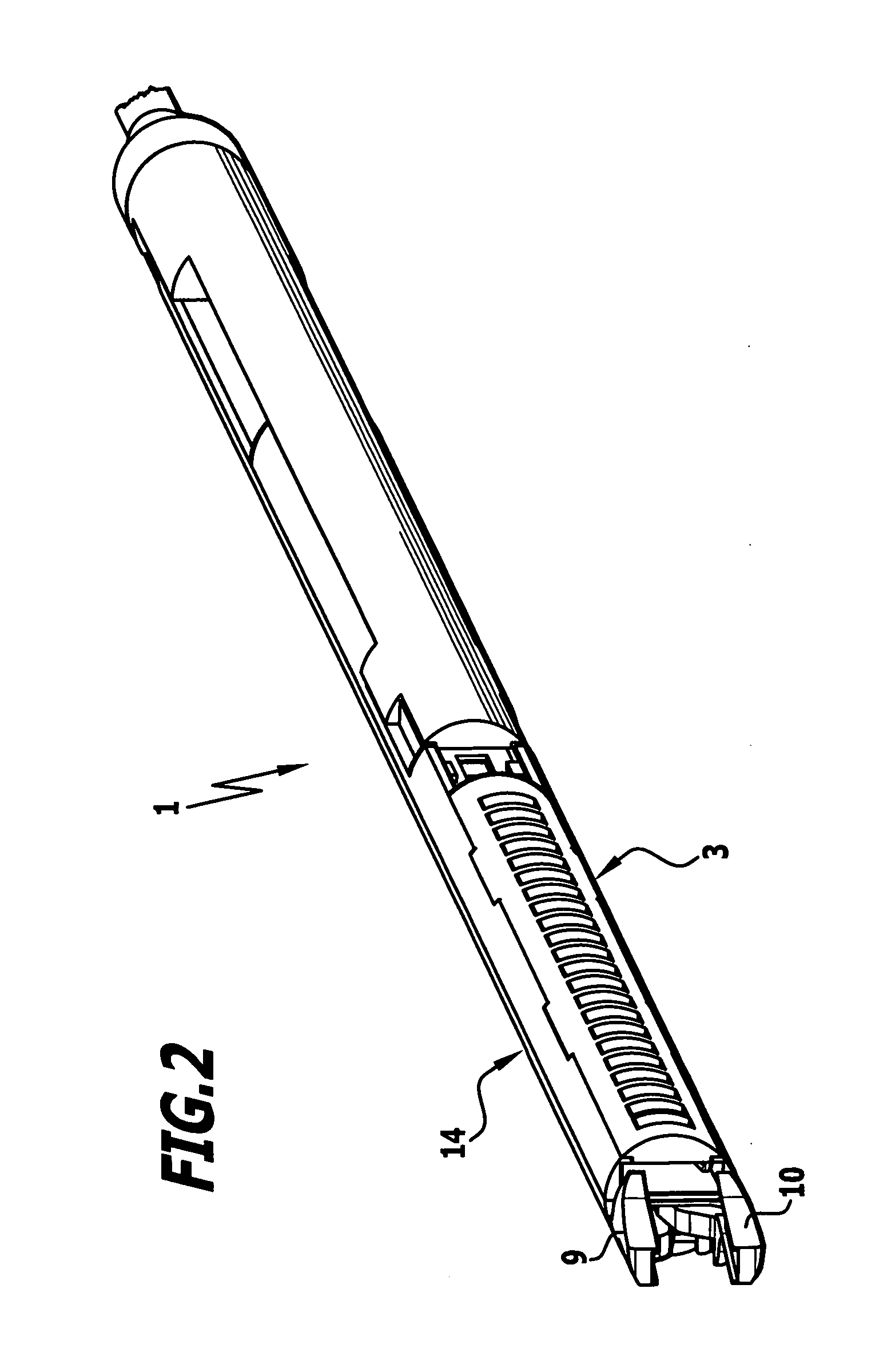
[0034]The instrument 1 shown in the drawing comprises a tubular barrel 2, of which only the distal end is shown in the drawing. At its proximal end not shown in the drawing, the barrel 2 is connected to a handle, on which activation elements are arranged, by means of which the transmission elements passing through the barrel, e.g. push and pull rods, can be moved, the movement of which can thus be transmitted to the distal end of the barrel 2.

A cartridge 3, which substantially has a semicircular cross-section and in which a plurality of C-shaped ligature clips 4 are arranged, is inserted into the barrel 2 at its distal end. These ligature clips have two legs 5, 6 arranged next to one another and at a spacing from one another, which are connected to one another at their proximal end by means of a bridge section 7. They are made from permanently deformable material, in particular metal, e.g. titanium or a titanium alloy, and the legs 5, 6 can be pressed towards one another out of an o...


PUM


Abstract

In order to maximise the pivoting range of the arms in a surgical instrument for the placement of C-shaped ligature clips having two legs connected to one another by means of a bridge section with two clamping jaws, which in an open position receive an open ligature clip between them and are movable into a closed position by approaching one another and in so doing close the ligature clips by their legs approaching one another, with two elastically deformable arms, each bearing a clamping jaw at its distal end, and with a slide, which is displaceable relative to the arms in the longitudinal direction thereof, and which abuts against the abutment surfaces of the arms and as a result of this abutment against the abutment surfaces elastically pivots the arms relative to one another in a pivoting plane out of a starting position into an end position upon displacement of the slide relative to the arms, in association with a small size of the instrument, it is proposed that at least over a part of their length and at least over a part of their width the two arms are arranged in planes running parallel to the pivoting plane and displaced relative to one another and overlap one another at least partially.

Description

[0001]This application claims the benefit of German Patent Application No. 10 2009 018 818.5 filed on Apr. 24, 2009.[0002]The present disclosure relates to the subject matter disclosed in German patent application No. 10 2009 018 818.5 of Apr. 24, 2009, which is incorporated herein by reference in its entirety and for all purposes.BACKGROUND OF THE INVENTION[0003]The invention relates to a surgical instrument for the placement of C-shaped ligature clips having two legs connected to one another by means of a bridge section with two clamping jaws, which in an open position receive an open ligature clip between them and are movable into a closed position by approaching one another and in so doing close the ligature clips by their legs approaching one another, with two elastically deformable arms, each bearing a clamping jaw at its distal end, and with a slide, which is displaceable relative to the arms in the longitudinal direction thereof, and which abuts against the abutment surfaces...

Claims


Application Information

Patent Timeline
IPC IPC(8): A61B17/10
CPCA61B17/1285
Inventor DISCH, ALEXANDERMAYENBERGER, RUPERT
Owner AESCULAP AG
Why Eureka
Try Eureka