Fluid analysis method and fluid analysis device

a fluid analysis and fluid technology, applied in liquid/fluent solid measurement, machines/engines, instruments, etc., can solve the problems of difficult analysis of the normal stress difference of low-viscosity fluid, difficulty in determining the normal stress difference, and inability to measure the normal stress difference of chemical fiber and plastic molding processes

Inactive Publication Date: 2010-10-28
NAT UNIV CORP NAGAOKA UNIV TECH
View PDF3 Cites 20 Cited by
  • Summary
  • Abstract
  • Description
  • Claims
  • Application Information

AI Technical Summary

Benefits of technology

[0008]In view of the above problems, it is an object of the present invention to provide a viscosity measuring method and a viscosity measuring device by which the normal stress difference not only of the high-viscosity fluid but also of the low-viscosity fluid can be easily analyzed.
[0015]According to the first to fourth aspects of the present invention, the shearing fluidity is applied to the fluid within the container by pushing the bob into the container and then the normal stress difference of the fluid is determined based on the reactive force which has been obtained at that time and was applied to the bob. Hence, the normal stress difference can be certainly determined even for the low-viscosity fluid hard to form into a solid state, thus permitting the normal stress difference to be easily analyzed with respect to the low-viscosity fluid in addition to the high-viscosity fluid.

Problems solved by technology

Whilst a rotating viscometer structured in this manner enables the measurement of shear viscosity, normal stress differences which largely affect formability in a molding process of chemical fiber and plastic have conventionally been unable to be measured.
However, with respect to a low-viscosity fluid that is hard to be formed into a solid state and thus hard to be sandwiched between the conical unit and the discoid unit, the low-viscosity fluid outflows between the conical unit and the discoid unit, resulting in a difficulty in determining the normal stress difference thereof.
Therefore, there has been a problem that the normal stress difference of the low-viscosity fluid is hard to analyze.

Method used


Image

  • Fluid analysis method and fluid analysis device
  • Fluid analysis method and fluid analysis device
  • Fluid analysis method and fluid analysis device

Examples


Embodiment Construction

[0024]Next is a description of a preferred embodiment of the present invention with reference to the accompanying drawings.

(1) Outline of Normal Stress Difference Measurement

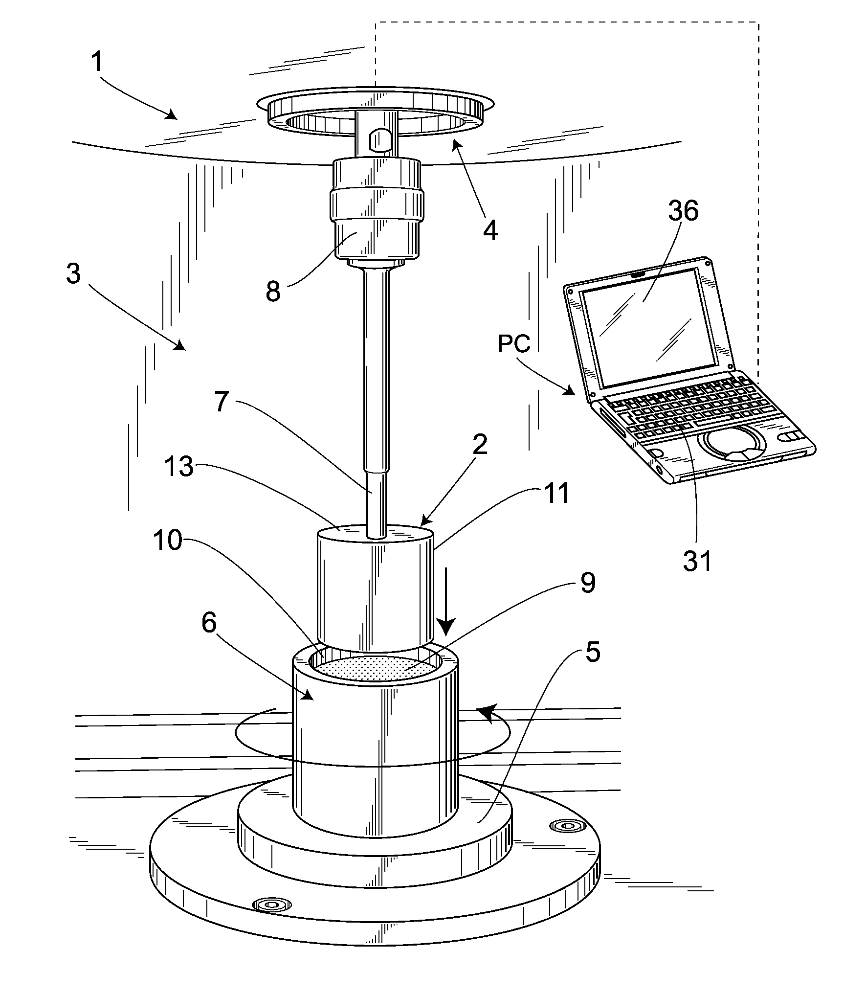
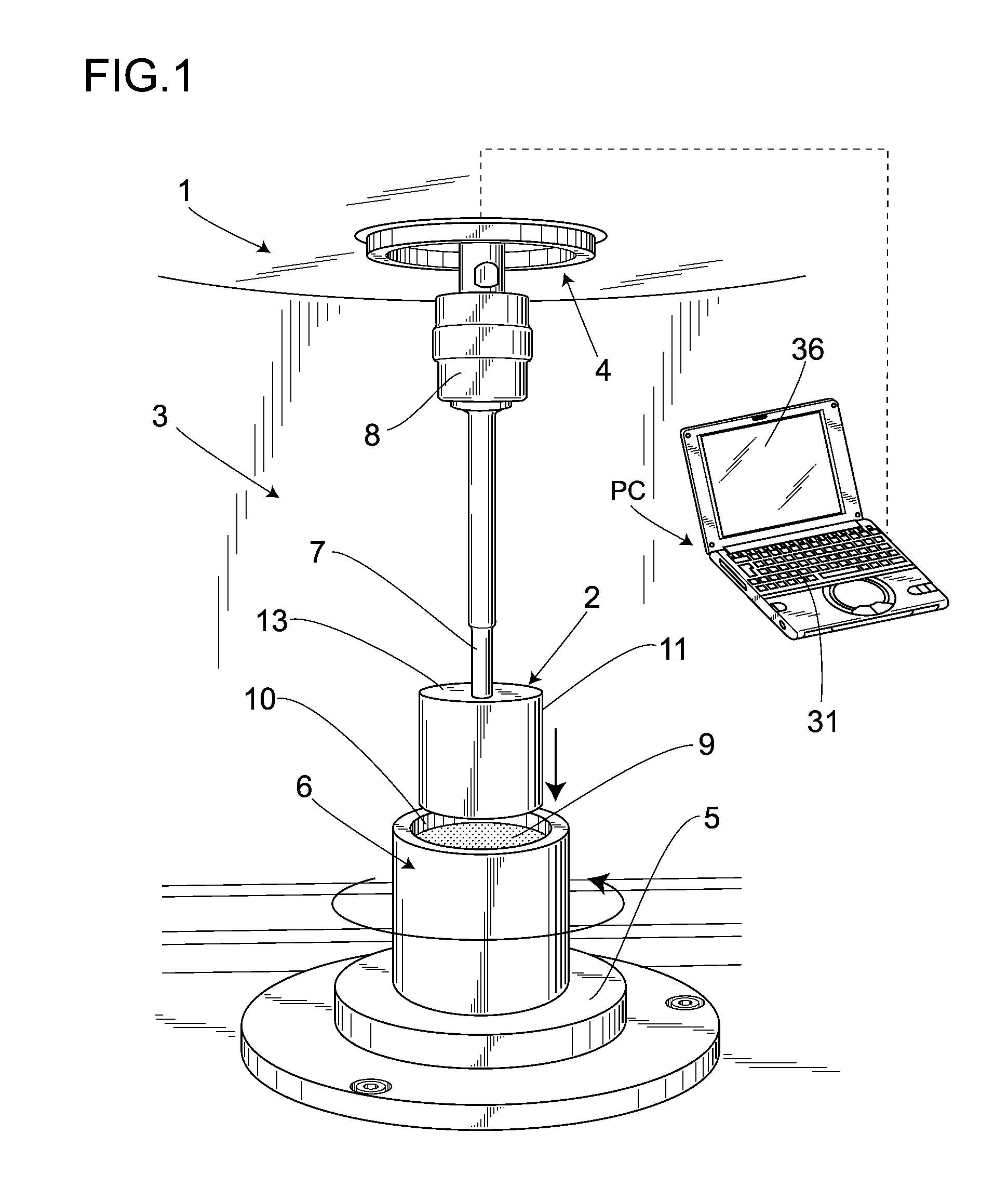
[0025]In FIG. 1, numeral symbol 1 denotes a viscosity measuring device which performs a fluid analysis method according to the present invention. This viscosity measuring device 1 is made up of a rotating viscometer (hereinafter simply referred to as a viscometer) 3 which has heretofore been employed for measuring viscosity of a fluid and a personal computer PC which is connected with the viscometer and has been loaded with a normal stress difference processing program for measuring a normal stress difference of the fluid.

[0026]In practice, the viscometer 3 is composed of an elevating motion driving unit 4 acting as a push-in means, a basal platform 5, and a container 6 located on the basal platform 5. The elevating motion driving unit 4 is mounted with a rod-like bob supporting member 7 in such a manner as to a...


PUM

PropertyMeasurementUnit
timeaaaaaaaaaa
timeaaaaaaaaaa
velocityaaaaaaaaaa

Abstract

There is provided a fluid analysis method and its device which are capable of easily analyzing a normal stress difference of a low-viscosity fluid in addition to that of a high-viscosity fluid. A shearing fluidity is applied to a non-Newtonian fluid within a lateral-side gap by pushing a cylindrical bob into a container. At that time, reactive force applied to the cylindrical bob is measured. Then, by practicing an arithmetic process in a given form using the reactive force and each of conditions input by a user, the normal stress difference of the low-viscosity non-Newtonian fluid which is hard to form in a solid state can be certainly determined. Thus, with respect to the low-viscosity non-Newtonian fluid in addition to the high-viscosity non-Newtonian fluid, the normal stress difference can be easily analyzed.

Description

CROSS-REFERENCE TO PRIOR APPLICATIONS[0001]This is a U.S. national phase application under 35 U.S.C. §371 of International Patent Application No. PCT / JP2006 / 326044, filed Dec. 27, 2006, and claims the benefit of Japanese Application No. 2006-053935, filed Feb. 28, 2006, both of which are incorporated by reference herein. The International Application was published in Japanese on Sep. 7, 2007 as International Publication No. WO 2007 / 099687 A1 under PCT Article 21(2).FIELD OF THE INVENTION[0002]The present invention relates to a fluid analysis method and a fluid analysis device, which are suitably applied to a viscometric measurement device employed for analyzing, e.g., a non-Newtonian fluid.BACKGROUND OF THE INVENTION[0003]Heretofore, a rotating viscometer has been known in which after immersing a cylindrical bob (a rotor) fitted on a rotating shaft in a fluid to be measured, the rotating shaft is rotated and thus the viscosity of the fluid is measured based on a viscous drag force a...

Claims


Application Information

Patent Timeline
Patent Type & Authority Applications(United States)
IPC IPC(8): G01N11/10
CPCG01N11/10G01N2203/0676G01N2011/0026
Inventor TAKAHASHI, TSUTOMUSHIRAKASHI, MASATAKAKAWANO, TOSHIHIRO
Owner NAT UNIV CORP NAGAOKA UNIV TECH
Why Eureka
Try Eureka