Automated Systems for Manufacturing Patient-Specific Orthopedic Implants and Instrumentation

Inactive Publication Date: 2010-10-28
CONFORMIS
View PDF99 Cites 185 Cited by
  • Summary
  • Abstract
  • Description
  • Claims
  • Application Information

AI Technical Summary

Benefits of technology

[0028]Optionally, the system can allow the user to fine-tune

Problems solved by technology

However, these are not truly personalized, pa

Method used


Image

  • Automated Systems for Manufacturing Patient-Specific Orthopedic Implants and Instrumentation
  • Automated Systems for Manufacturing Patient-Specific Orthopedic Implants and Instrumentation
  • Automated Systems for Manufacturing Patient-Specific Orthopedic Implants and Instrumentation

Examples


Embodiment Construction

[0063]Various embodiments of the invention can be adapted and applied to implants and other devices associated with any anatomical joint including, without limitation, a spine, spinal articulations, an intervertebral disk, a facet joint, a shoulder joint, an elbow, a wrist, a hand, a finger joint, a hip, a knee, an ankle, a foot and toes. Furthermore, various embodiments can be adapted and applied to implants, instrumentation used during surgical or other procedures, and methods of using various patient-specific implants, instrumentation and other devices.

[0064]One embodiment is a nearly-fully automated system to design a patient-specific implant that requires minimal input from a designer or other operator and that is capable of designing an implant in a small fraction of the time it takes for a designer to design such an implant using computer aided design (CAD) tools.

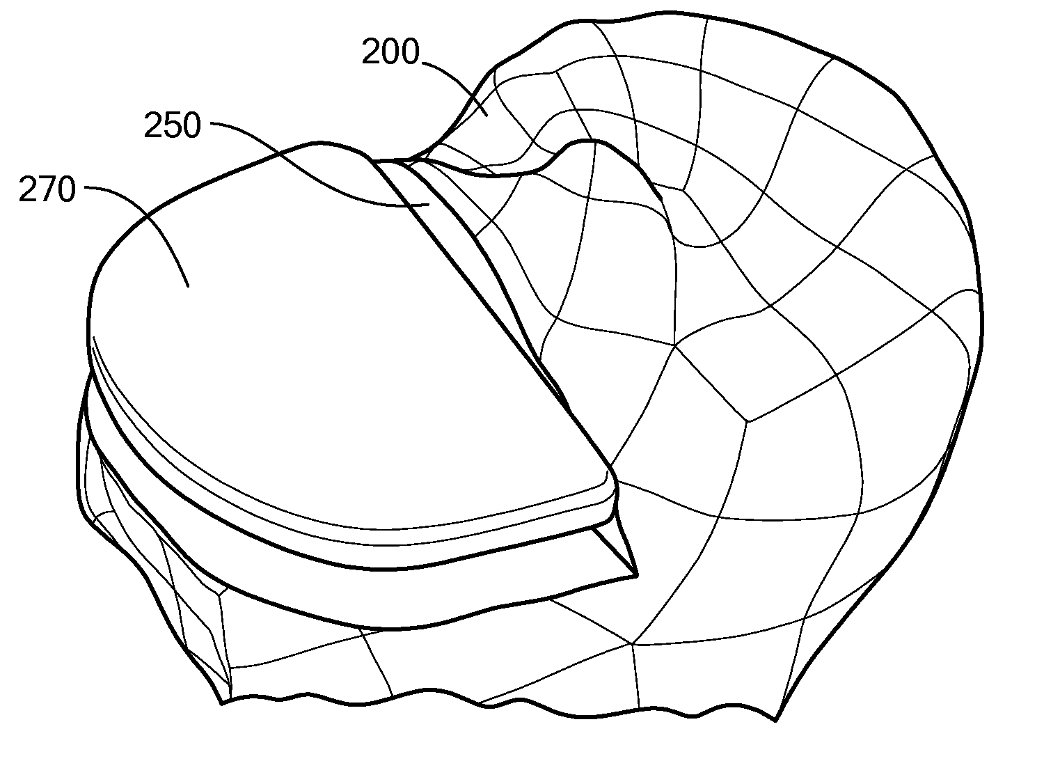
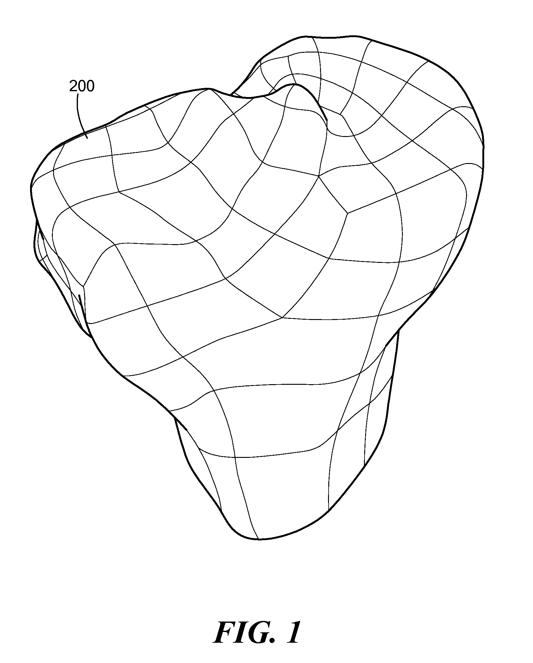
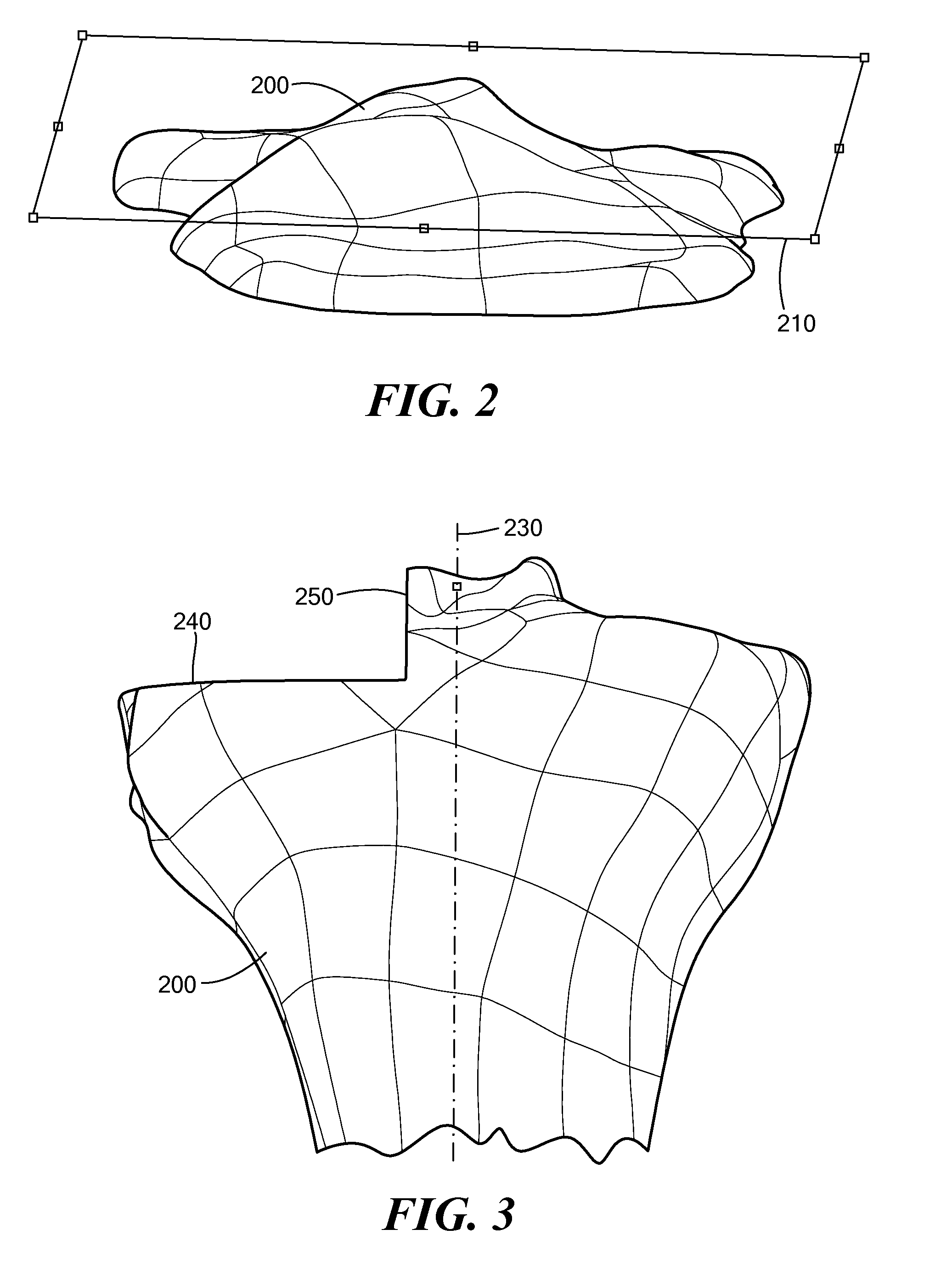
Automated Design of a Patient-Specific Unicompartmental Femoral Implant

[0065]Referring to FIGS. 1-13 below, an exe...


PUM


Abstract

Disclosed herein are devices, systems and methods for the automated design and manufacture of patient-specific/patient-matched orthopedic implants. While the embodiments described herein specifically pertain to unicompartmental resurfacing implants for the knee, the principles described are applicable to other types of knee implants (including, without limitation, other resurfacing implants and joint replacement implants) as well as implants for other joints and other patient-specific orthopedic applications.

Description

RELATED APPLICATIONS[0001]This application claims priority to U.S. Provisional Application 61 / 208,440, filed Feb. 24, 2009, entitled “Automated Systems for Manufacturing Patient-Specific Orthopedic Implants and Instrumentation.”[0002]This application claims priority to U.S. Provisional Application 61 / 208,444, filed Feb. 24, 2009, entitled “Automated Systems for Manufacturing Patient-Specific Orthopedic Implants and Instrumentation.”[0003]This application is a continuation-in-part application of U.S. patent application No. U.S. Ser. No. 11 / 671,745, filed Feb. 6, 2007, entitled “Patient Selectable Joint Arthroplasty Devices and Surgical Tools”, which in turn claims the benefit of U.S. Ser. No. 60 / 765,592 entitled “Surgical Tools for Performing Joint Arthroplasty” filed Feb. 6, 2006; U.S. Ser. No. 60 / 785,168, entitled “Surgical Tools for Performing Joint Arthroplasty” filed Mar. 23, 2006; and U.S. Ser. No. 60 / 788,339, entitled “Surgical Tools for Performing Joint Arthroplasty” filed Ma...

Claims


Application Information

Patent Timeline
IPC IPC(8): G06F17/50
CPCA61B17/1662A61B17/1675A61B2017/00526A61B2019/508A61F2/30942A61F2/38G06F17/50A61F2002/30943A61F2002/30945A61F2002/30948A61F2002/30952A61F2002/3895A61F2002/30878A61B2034/108A61F2/3859G06F30/00
Inventor STEINES, DANIELZHURAVLEV, ALEXEY
Owner CONFORMIS
Why Eureka
Try Eureka