
Memory system

a memory system and memory technology, applied in the field of memory systems, can solve the problems of reducing the useable block and the inability to effectively use the storage area of flash memory

Inactive Publication Date: 2010-10-28
KK TOSHIBA
View PDF9 Cites 23 Cited by
  • Summary
  • Abstract
  • Description
  • Claims
  • Application Information

AI Technical Summary

Benefits of technology

This patent describes a memory system that includes a cache memory and two nonvolatile semiconductor memories. The system has two input buffers for data buffering between the nonvolatile memories and the cache memory. The controller allocates storage areas and input buffers to the nonvolatile memories based on logical block units associated with one or more blocks. The system also includes processing for writing data in a sector unit, flushing data to the input buffers, relocating logical blocks, and flushing data from the nonvolatile memories to the input buffers. The technical effect of this patent is to improve the performance and reliability of a memory system by optimizing data buffering and allocation, and improving data flushing and relocation processes.

Problems solved by technology

When the blocks in such a porous state increases, substantially usable blocks decrease and a storage area of the flash memory cannot be effectively used.
However, when the compaction processing or the like takes time, the data flush from the cache memory to the flash memory has to be put on wait.

Method used


Image

  • Memory system
  • Memory system
  • Memory system

Examples


embodiments

[0053]Embodiments of the present invention are explained below with reference to the drawings. In the following explanation, components having the same functions and configurations are denoted by the same reference numerals and signs. Redundant explanation of the components is performed only when necessary.

[0054]First, terms used in this specification are defined.

[0055]Physical page: A unit that can be collectively written and read out in a NAND memory chip. A physical page size is, for example, 4 kB. However, a redundant bit such as an error correction code added to main data (user data, etc.) in an SSD is not included. Usually, 4 kB+redundant bit (e.g., several 10 B) is a unit simultaneously written in a memory cell. However, for convenience of explanation, the physical page is defined as explained above.

[0056]Logical page: A writing and readout unit set in the SSD. The logical page is associated with one or more physical pages. A logical page size is, for example, 4 kB in an 8-bi...

first embodiment

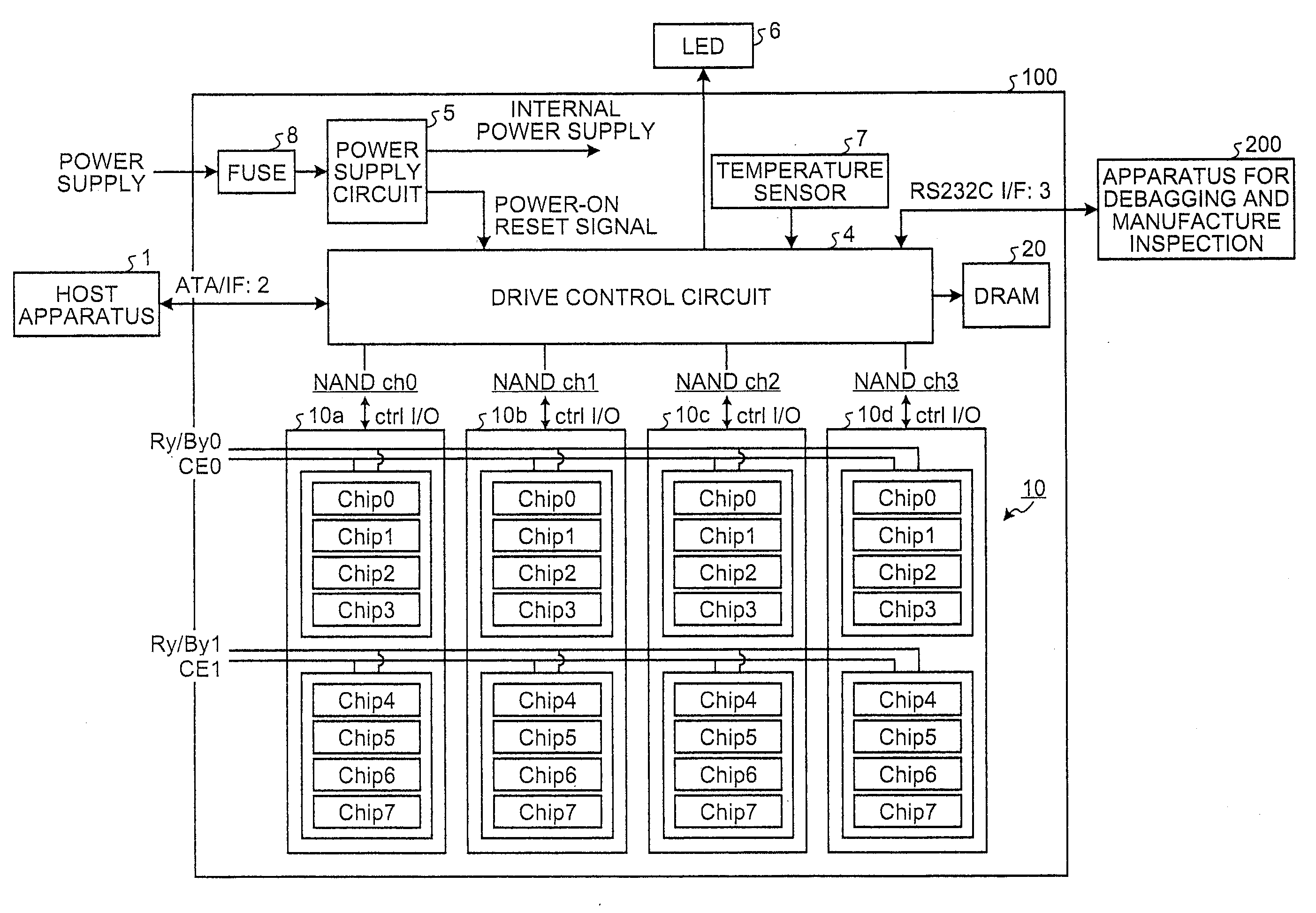
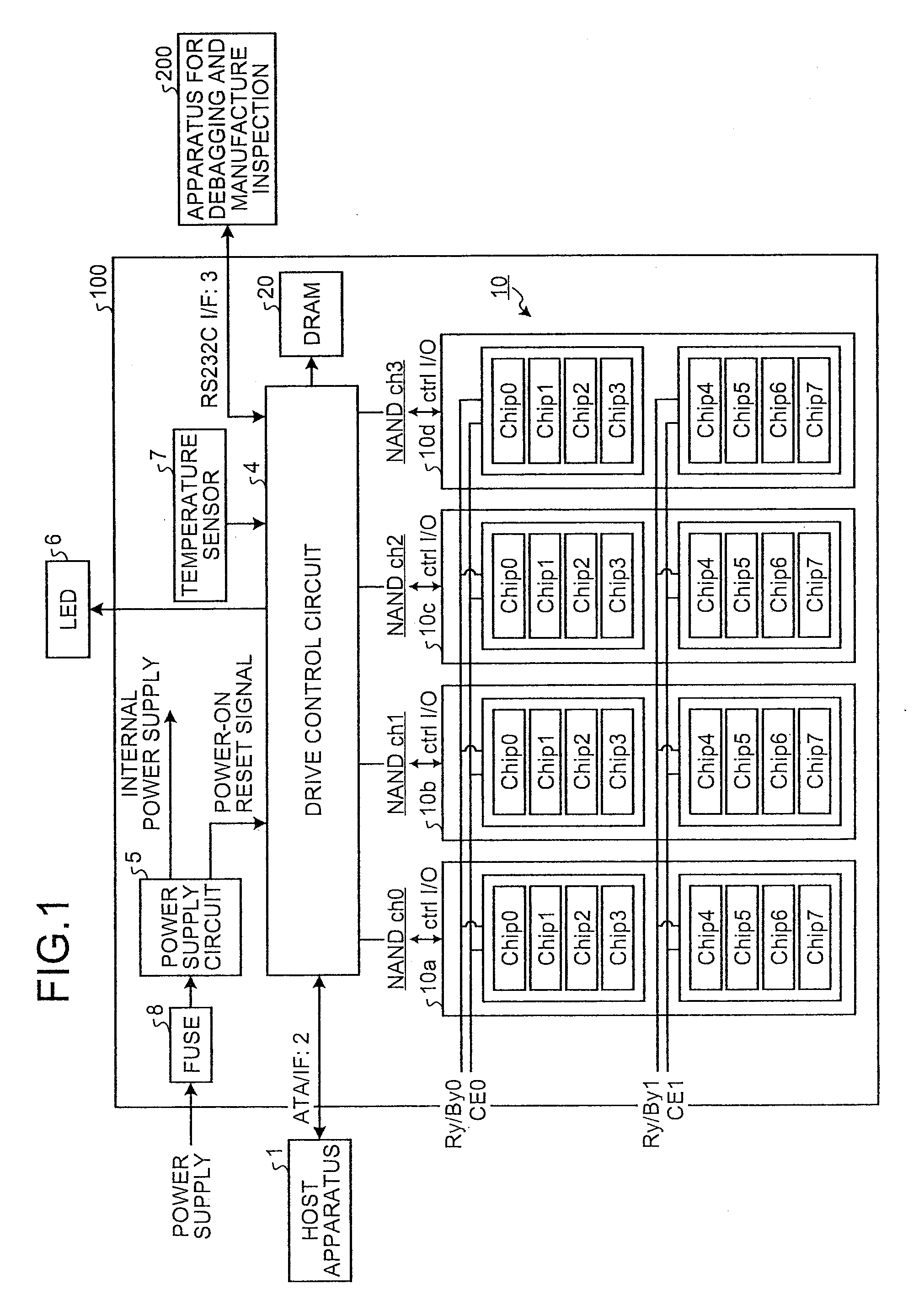
[0070]FIG. 1 is a block diagram of a configuration example of an SSD (Solid State Drive) 100. The SSD 100 is connected to a host apparatus 1 such as a personal computer or a CPU core via a memory connection interface such as an ATA interface (ATA I / F) 2 and functions as an external storage of the host apparatus 1. The SSD 100 can transmit data to and receive data from an apparatus for debagging and manufacture inspection 200 via a communication interface 3 such as an RS232C interface (RS232C I / F). The SSD 100 includes a NAND-type flash memory (hereinafter abbreviated as NAND memory) 10 as a nonvolatile semiconductor memory, a drive control circuit 4 as a controller, a DRAM 20 as a volatile semiconductor memory, a power supply circuit 5, an LED for state display 6, a temperature sensor 7 that detects the temperature in a drive, and a fuse 8.

[0071]The power supply circuit 5 generates a plurality of different internal DC power supply voltages from external DC power supplied from a powe...


PUM


Abstract

A controller executes first processing for writing a plurality of data in a sector unit in the first storing area; second processing for flushing the data stored in the first storing area to the first input buffer in a first management unit twice or larger natural number times as large as the sector unit; third processing for flushing the data stored in the first storing area to the second input buffer in a second management unit twice or larger natural number times as large as the first management unit; fourth processing for relocating a logical block in which all pages are written in the first input buffer to the second storing area; fifth processing for relocating a logical block in which all pages are written in the second input buffer to the third storing area; and sixth processing for flushing a plurality of data stored in the second storing area to the second input buffer in the second management unit.

Description

TECHNICAL FIELD[0001]The present invention relates to a memory system including a nonvolatile semiconductor memory.BACKGROUND ART[0002]As an external storage device used in a computer system, an SSD (Solid State Drive) mounted with a nonvolatile semiconductor memory such as a NAND-type flash memory attracts attention. The flash memory has advantages such as high speed and light weight compared with a magnetic disk device.[0003]The SSD includes a plurality of flash memory chips, a controller that performs read / write control for the respective flash memory chips in response to a request from a host apparatus, a buffer memory for performing data transfer between the respective flash memory chips and the host apparatus, a power supply circuit, and a connection interface to the host apparatus (e.g., Patent Document 1).[0004]Examples of the nonvolatile semiconductor memory include nonvolatile semiconductor memories in which a unit of erasing, writing, and readout is fixed such as a nonvol...

Claims


Application Information

Patent Timeline
Patent Type & Authority Applications(United States)
IPC IPC(8): G06F12/00G06F12/02
CPCG06F12/0246G06F12/0804G06F12/0866G06F2212/7205G06F2212/1016G06F2212/7203G06F12/0897G06F12/00G06F12/08G06F13/10
Inventor YANO, JUNJIMATSUZAKI, HIDENORIHATSUDA, KOSUKE
Owner KK TOSHIBA
Learn More