Systems and Methods for Rapid Turbine Deceleration

a technology of rapid turbine deceleration and turbine blades, which is applied in the direction of engine starters, turbine/propulsion engine ignition, machines/engines, etc., can solve the problems of reducing the flow of fuel, reducing not providing a direct relationship with the speed of the rotor, so as to limit the flow of air

Inactive Publication Date: 2010-11-04
GENERAL ELECTRIC CO
View PDF8 Cites 14 Cited by
  • Summary
  • Abstract
  • Description
  • Claims
  • Application Information

AI Technical Summary

Benefits of technology

[0008]The present application further provides a method for shutting down a gas turbine engine system. The method may include the steps of reducing a flow of fuel to a combustor, reversing the operation of a generator so as to apply torque to a rotor, and increasing the deceleration of the rotor so as to limit a flow of air into the gas turbine engine system.
[0009]The present application further provides a gas turbine engine system for turbine deceleration during shutdown procedures. The gas turbine engine system may include a rotor extending through a turbine, a compressor in communication with the rotor for producing a flow of air, a generator engaged with the rotor, and a starting system in communication with the rotor. The starting system may reverse the operation of the generator via a load commutating inverter so as to apply torque to the rotor during the shutdown procedures so as to limit the flow of air.

Problems solved by technology

Reducing the flow of fuel over time, however, does not provide a direct relationship with the speed of the rotor.
Rather, variations in the speed of the rotor versus time may result.
Specifically, uncontrolled and varying fuel to air ratios may result in variations in firing temperatures, exhaust temperatures, and resultant emission rates.
Moreover, existing shutdown procedures may result in a “cool” stator and a “hot” rotor and other components for some period of time until the respective thermal states normalize as a cooler flow of air passes through the turbine.
The additional clearances, however, generally result in a loss of overall turbine performance.
These thermal transients also may promote part fatigue and, hence, reduced part lifetime.

Method used


Image

  • Systems and Methods for Rapid Turbine Deceleration
  • Systems and Methods for Rapid Turbine Deceleration

Examples


Embodiment Construction

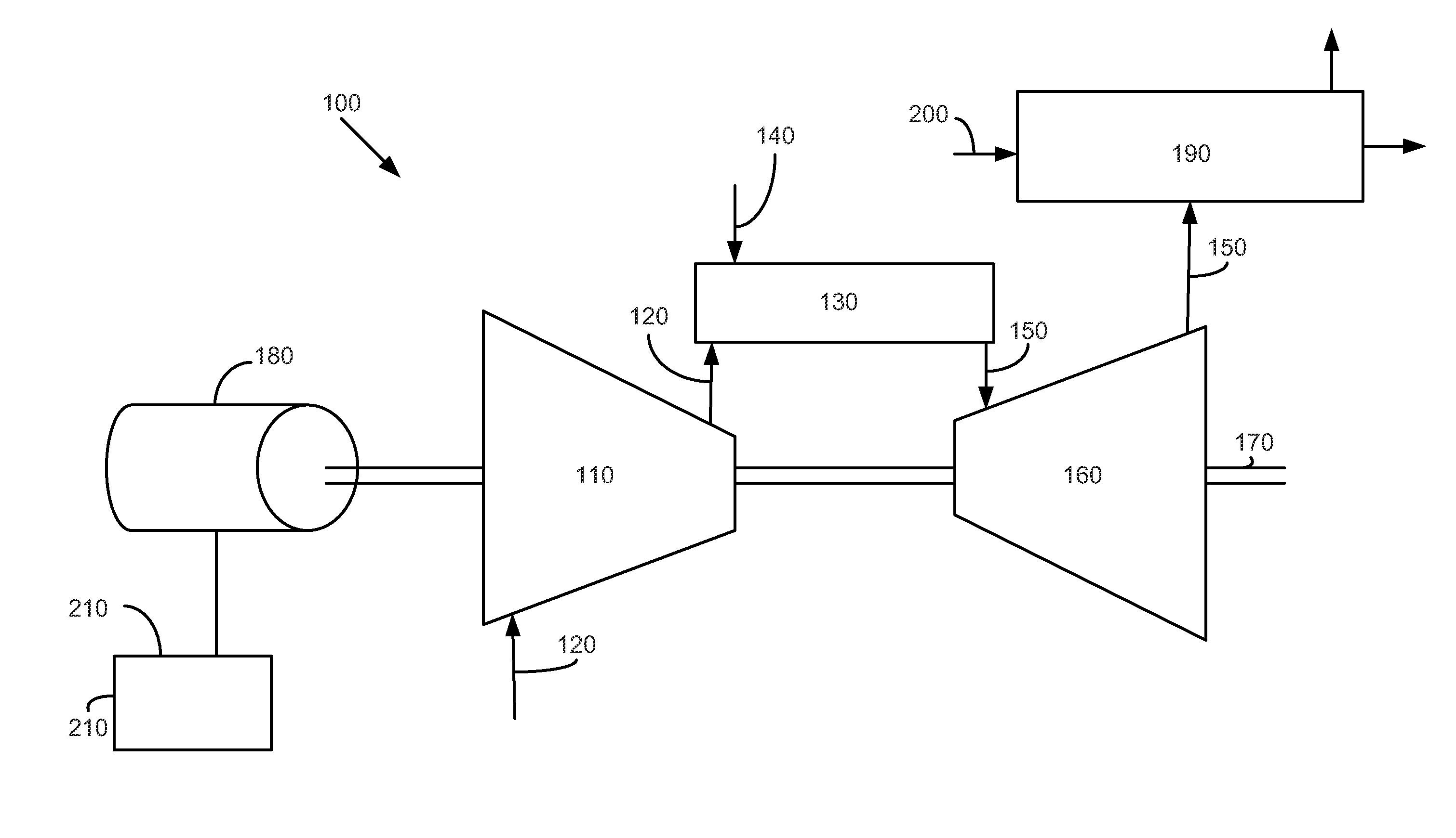
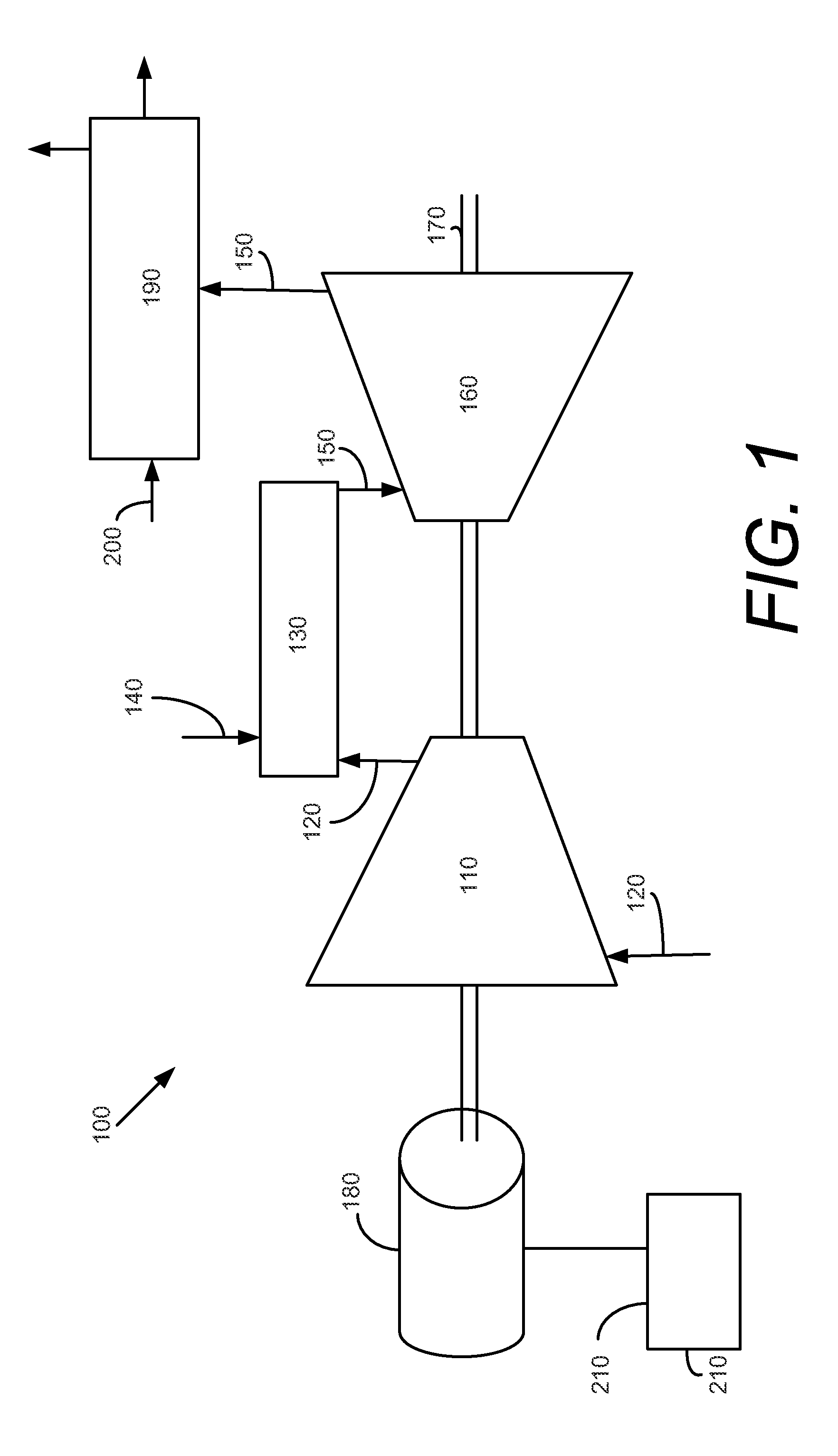
[0012]Referring now to the drawing, in which like numbers refer to like elements, FIG. 1 shows a schematic view of a gas turbine engine 100 as may be described herein. The gas turbine engine 100 may include a compressor 110. The compressor 110 compresses an incoming flow of air 120. The compressor 110 delivers the compressed flow of air 120 to a combustor 130. The combustor 130 mixes the compressed flow of air 120 with a compressed flow of fuel 140 and ignites the mixture to create a flow of combustion gases 150. Although only a single combustor 130 is shown, the gas turbine engine 100 may include a number of combustors 130. The flow of combustion gases 150 are in turn delivered to a turbine 160. The flow of combustion gases 150 drives the turbine 160 so as to produce mechanical work via the turning of a turbine rotor 170. The mechanical work produced in the turbine 160 drives the compressor 110 and an external load such as an electrical generator 180 and the like via the turbine ro...


PUM


Abstract

The present application provides for a gas turbine engine system for turbine deceleration during shutdown procedures. The gas turbine engine system may include a rotor extending through a turbine, a generator engaged with the rotor, and a starting system in communication with the rotor. The starting system may reverse the operation of the generator so as to apply torque to the rotor during the shutdown procedures.

Description

RELATED APPLICATIONS[0001]The present application is a continuation in part of U.S. Ser. No. 12 / 434,755, filed on May 4, 2009, and entitled “GAS TURBINE SHUTDOWN”. U.S. Ser. No. 12 / 434,755 is incorporated herein by reference in full.TECHNICAL FIELD[0002]The present application relates generally to gas turbine engines and more particularly relates to systems and methods for increasing the rate of deceleration of a turbine rotor and other components during turbine shutdown procedures so as to limit the intake of air therethrough.BACKGROUND OF THE INVENTION[0003]A common approach to gas turbine engine shutdown is to reduce the flow of fuel gradually over time. Once the flow of fuel and / or the rotor speed is sufficiently low for a particular turbine, the fuel flow may be stopped and the turbine decelerates to a minimum speed. This minimum speed may be known as the “turning gear speed”, i.e., the speed at which the rotor must be continually turned by an outside source so as to prevent th...

Claims


Application Information

Patent Timeline
Patent Type & Authority Applications(United States)
IPC IPC(8): F02C7/268F02C7/26F02C7/00
CPCF01D21/00F01D21/14F02C7/268F02C9/48F05D2220/76F05D2260/903F05D2260/85F05D2270/304F02C9/56
Inventor SNIDER, DAVID AUGUSTMEMMER, JOHN DAVID
Owner GENERAL ELECTRIC CO
Why Eureka
Try Eureka