Fabric architectures for improved ballistic impact performance

a technology of fabric architecture and ballistic impact, applied in the direction of weaving, protective fabrics, other domestic articles, etc., can solve the problems of reducing v50 performance, reducing production cost, and not providing adequate backface deformation resistan

Inactive Publication Date: 2010-11-04
EGRES JR RONALD G
View PDF33 Cites 43 Cited by
  • Summary
  • Abstract
  • Description
  • Claims
  • Application Information

AI Technical Summary

Problems solved by technology

One challenge for body armor manufacturers is to provide adequate protection from a particular threat or threats that the wearer may be subjected to in the field, while minimizing the weight, or areal density of the protective garment so as not to impede the dexterity of the wearer.
While the ballistic performance requirements set forth above can be achieved using any of several commercially available anti-ballistic materials, or combinations of said materials, the challenge for soft body armor manufactures is the selection and arrangement of ballistic layers required to prevent penetration with an acceptable safety margin and minimize backface deformation while also minimizing the weight, bulk and stiffness of the armor to improve comfort.
Such articles are prepared from combinations of high tenacity fibers, matrix resins and films, often making them more costly to produce.
Meeting the minimum ballistic performance requirements using only the above woven fabrics presents a challenge for ballistic armor manufacturers.
While many low cover factor (loosely woven) ballistic resistant fiber yarn fabrics provide satisfactory V50 performance at the desired areal density (vests fabricated therefrom can be shown to repeatedly impede projectiles from penetrating the vest material at velocities safely above the threshold values outlined in NIJ Standard-0101.04), they do not provide adequate backface deformation resistance.
Conversely, the use of higher cover factor (more tightly woven) ballistic resistant fiber yarn fabrics at the same vest areal density while improving backface deformation performance, often results in significant reduction in V50 performance, sometimes falling below the NIJ Standard-0101.04 velocities required for backface signature measurement.
While the addition of these layers has been shown to improve the backface signature performance of an armor material, they can often have a deleterious effect on V50 performance.
In addition, the resin adds to the weight and stiffness of the ballistic vest assembly.
Due to this “sidedness” these hybrid ballistic vest constructions can be inadvertently worn inside-out, or inserted the wrong way into a tactical vest, providing less than optimal protection from projectile threats.

Method used


Image

  • Fabric architectures for improved ballistic impact performance
  • Fabric architectures for improved ballistic impact performance
  • Fabric architectures for improved ballistic impact performance

Examples


example 1

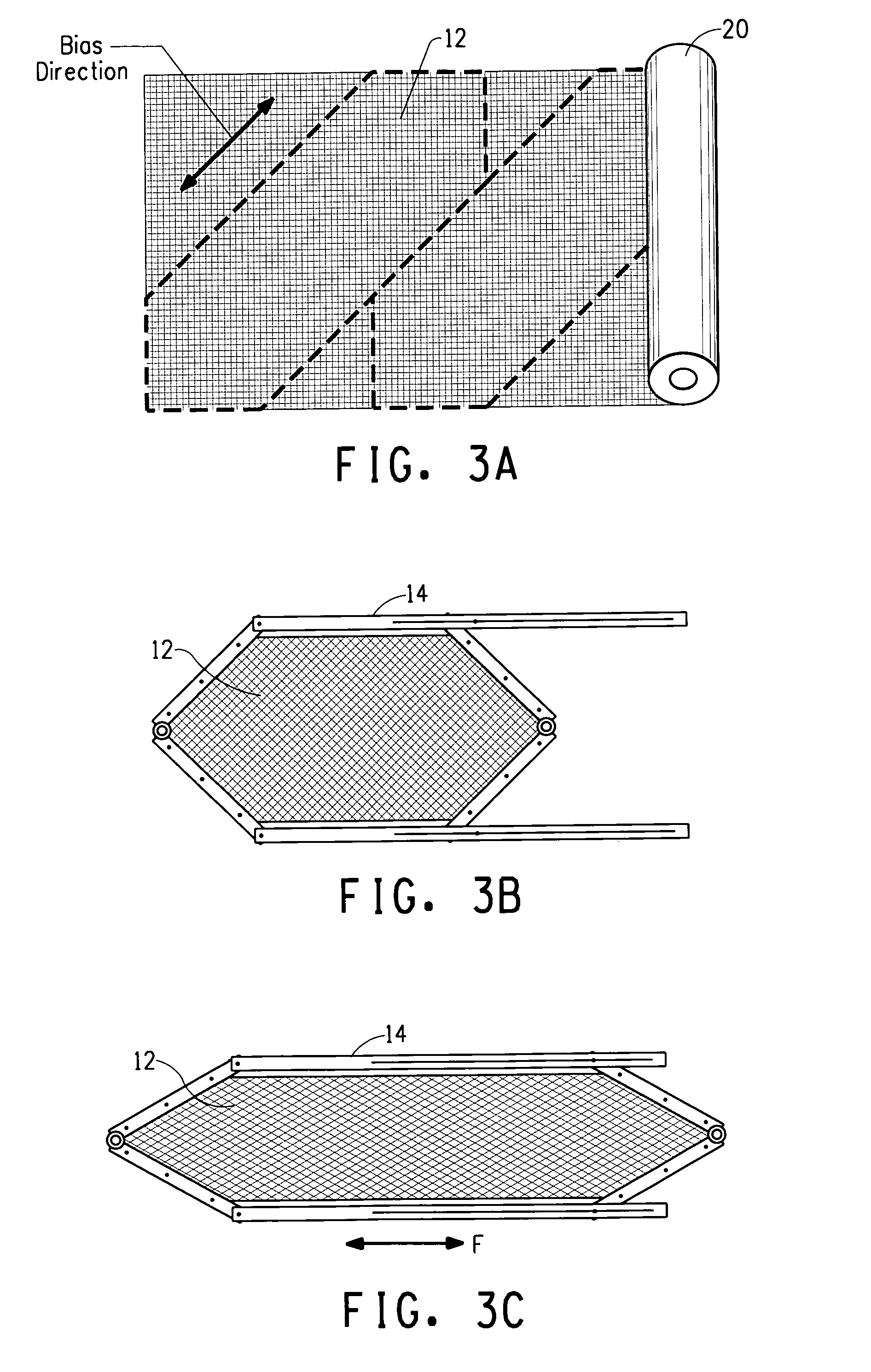
[0056]Diagonal strips were cut from a 63 in (160 cm) wide roll of the 840 denier Kevlar® 129 yarn, 18 ends per inch warp, 18 ends per inch fill greige fabric described in Comparative Example 2. The diagonal cuts were oriented along the bias direction of this plain weave fabric as shown in FIG. 3A; generating bias-oriented fabric strips 28 in (71 cm) in width. The fabric was clamped in a trellising frame as illustrated in FIG. 3B and extended to achieve a 45 degree acute trellis angle. The trellised fabric was cut into equal sections and cross-laid (stacked in an alternating layer fashion, with every layer having a trellis direction rotated 90 degrees relative to the one before it). The stack was constructed with the aid of a square pinning frame that held the trellis angle of individual fabric layers fixed during construction. This alternating cross-laid arrangement of fabric layers was repeated to create a stack with 26 trellised fabric layers. The stack of fabric layers were stitc...

example 2

[0057]Diagonal strips were cut from a 63 in (160 cm) wide roll of the 600 denier Kevlar® KM2 yarn, 17 ends per inch warp, 17 ends per inch fill greige fabric described in Comparative Example 2. The diagonal cuts were oriented along the bias direction of this plain weave fabric as shown in FIG. 3A, generating bias-oriented fabric strips. The fabric was clamped in a trellising frame as illustrated in FIG. 3B and extended to achieve a 30 degree acute trellis angle. The trellised fabric was cut into equal sections and cross-laid (stacked in an alternating layer fashion, with every layer having a trellis direction rotated 90 degrees relative to the one before it). The stack was constructed with the aid of a square pinning frame that held the trellis angle of individual fabric layers fixed during construction. This alternating cross-laid arrangement of fabric layers was repeated to create a stack with 27 trellised fabric layers. The stack of fabric layers were stitched together about thei...

example 3

[0058]A multilayer panel comprised of a trellised fabric architecture generated using the 20×20 ends per inch, 840 denier Kevlar® 129 yarn crow's foot weave fabric described in Comparative Example 6, was generated using the procedure described for Experimental example 1 above. The finished test panel was comprised of 23 layers, each having a 45 degree trellis angle, the layers being stacked in a 0 degree-90 degree alternating orientation as done in experimental example 1. The panel was sewn about the perimeter and with a 2 in×2 in (5.1×5.1 cm) quilt pattern. The backface signature and V50 results for 44 Magnum bullets at 1430±30 ft / s against a clay witness appear in Table 3.

[0059]This example exhibited improved backface without significant loss in V50 when compared with the target fabricated from the base fabric in Comparative Example 6.


PUM

PropertyMeasurementUnit
vertical anglesaaaaaaaaaa

Abstract

A woven fabric from yarn for use in the manufacture of ballistic projectile or puncture resistant articles where the fabric has a first plurality of parallel oriented yarns within the plane of the fabric interwoven with a second plurality of parallel oriented yarns within the plane of the fabric having a direction / orientation within the plane of the fabric different from that of the first plurality and where the crossing of any fiber yarn from the first plurality with a fiber yarn from the second plurality forms a pair of acute vertical angles having an angular measurement less than 90 degrees.

Description

BACKGROUND OF THE INVENTION[0001]1. Field of the Invention[0002]The present invention relates to fabric architectures and soft body armors constructed therefrom.[0003]2. Description of the Related Art[0004]Protective body armors such as those providing protection against ballistic and stab type threats have long been an area of significant interest. One challenge for body armor manufacturers is to provide adequate protection from a particular threat or threats that the wearer may be subjected to in the field, while minimizing the weight, or areal density of the protective garment so as not to impede the dexterity of the wearer.[0005]Characterization of the protective capabilities of any armor material against ballistic projectile threats, such as deformable bullets and non-deformable shrapnel, requires some determination of the ballistic velocity limit with respect to the material's areal density and size, as well as the properties of the projectile (mass, hardness, shape, etc.). On...

Claims


Application Information

Patent Timeline
Patent Type & Authority Applications(United States)
IPC IPC(8): F41H5/04D03D13/00
CPCB32B5/12D03D1/0052D03D13/002D03D15/00D03D15/0011D10B2101/06D10B2501/04D10B2101/12D10B2201/24D10B2321/02D10B2321/06D10B2321/10D10B2331/04D10B2101/08B32B5/022B32B5/024B32B5/04B32B5/06B32B5/26B32B7/12B32B27/12B32B2262/02B32B2262/0253B32B2262/0269B32B2262/0284B32B2262/101B32B2262/105B32B2262/106B32B2262/14B32B2307/50B32B2307/54B32B2307/558B32B2307/58B32B2307/718B32B2307/72B32B2571/02Y10T442/3179D03D15/267D03D15/283
Inventor EGRES, JR., RONALD G.
Owner EGRES JR RONALD G
Why Eureka
Try Eureka