Laser device for the ignition device of an internal combustion engine

Inactive Publication Date: 2010-11-04
ROBERT BOSCH GMBH
View PDF12 Cites 24 Cited by
  • Summary
  • Abstract
  • Description
  • Claims
  • Application Information

AI Technical Summary

Benefits of technology

[0004]The present invention relates to providing a laser device in which the surface temperatures of the combustion chamber window that arise

Problems solved by technology

However, it may happen that the necessary optical transparency of the combustion-chamber window is lost due to deposits of exhaust gas on the combustion-chamber window.
However, the surface temperature of the combustion-chamber window must

Method used


Image

  • Laser device for the ignition device of an internal combustion engine
  • Laser device for the ignition device of an internal combustion engine
  • Laser device for the ignition device of an internal combustion engine

Examples


Example

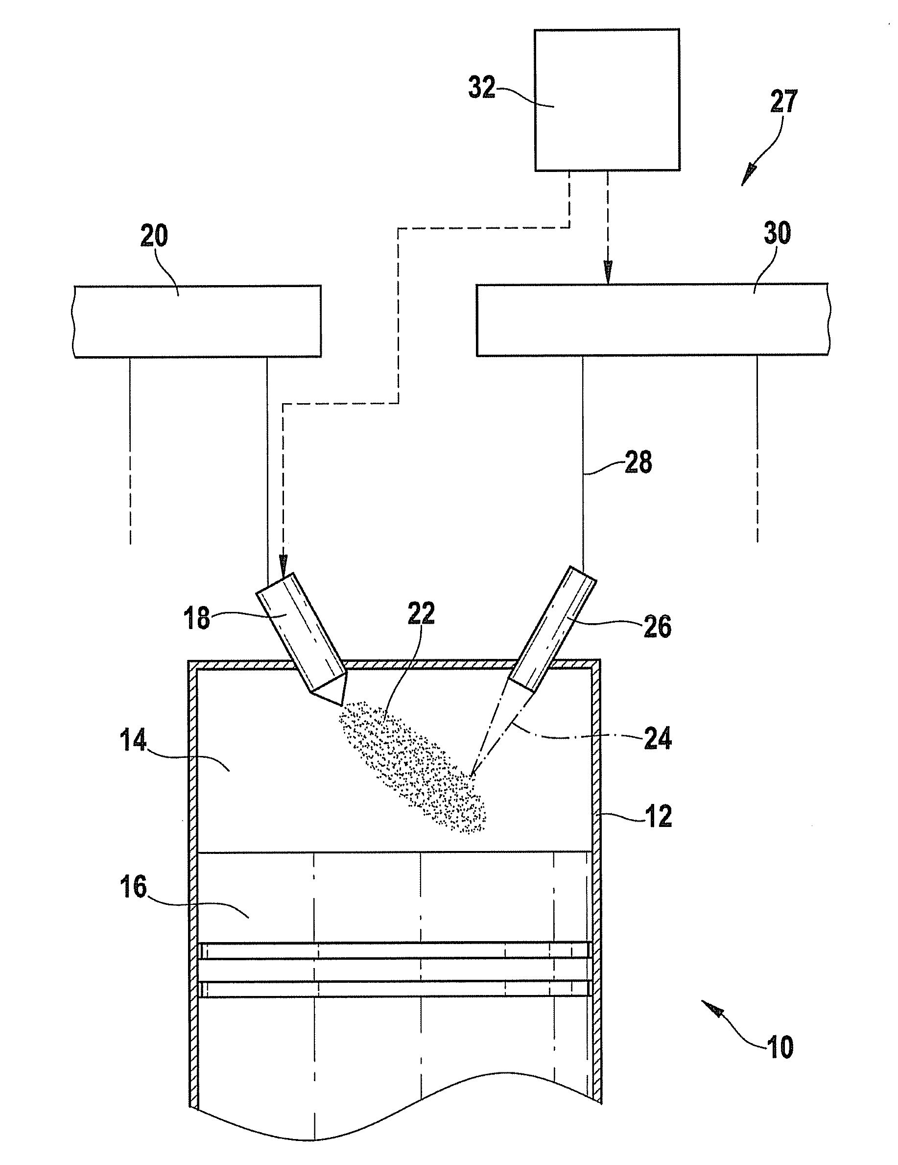
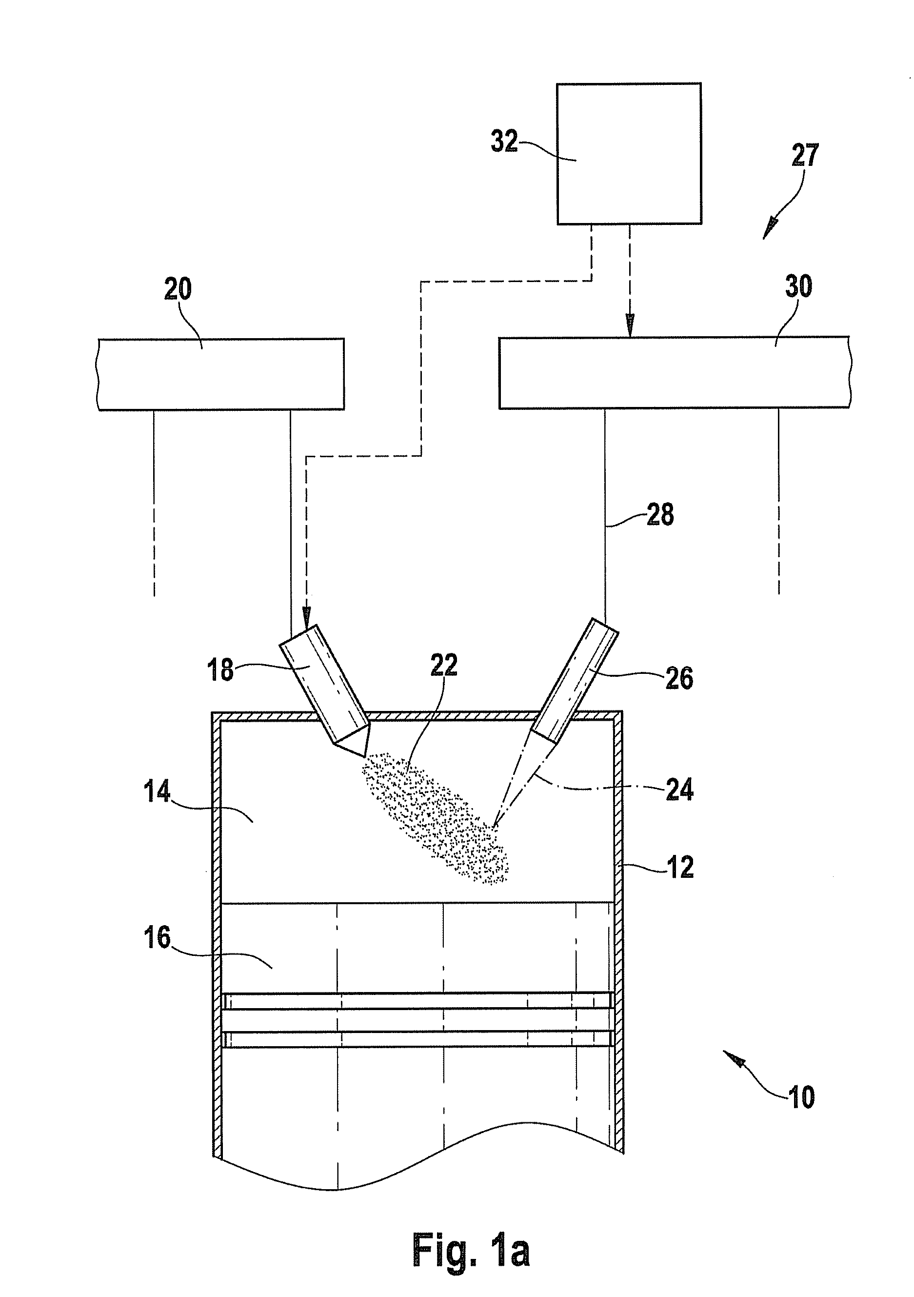
[0020]In FIG. 1a, an internal combustion engine in its entirety is denoted by reference numeral 10. It may be used for driving a motor vehicle. Internal combustion engine 10 includes one or a plurality of cylinders, of which only one, having a reference numeral 12, is shown in FIG. 1. A combustion chamber 14 of cylinder 12 is bounded by a piston 16. Fuel reaches combustion chamber 14 directly through an injector 18, which is connected to a fuel pressure reservoir 20 which is also referred to as a rail. As an alternative, the mixture formation may also take place outside of combustion chamber 14, e.g., in the intake manifold.

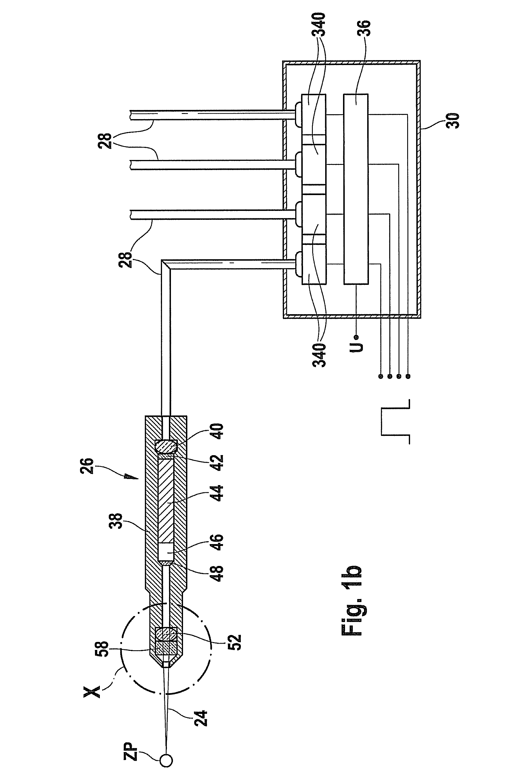
[0021]Fuel-air mixture 22 inside combustion chamber 14 is ignited by a laser pulse 24, which is radiated into combustion chamber 14 by an ignition device 27 which includes a laser device 26. For this purpose, an optical fiber device 28 feeds laser device 26 with pumped light from a pumping light source 30. Pumping light source 30 is controlled by a control device...


PUM


Abstract

A laser device of a so-called laser ignition is provided, in which the heat dissipation is improved between a combustion chamber window and a housing, and the cooling or temperature of the combustion chamber window is able to be adjusted within broad limits by simple modifications.

Description

BACKGROUND INFORMATION[0001]In a so-called laser ignition, a laser beam is focused into the combustion chamber of an internal combustion engine and ignites the fuel-air mixture present in the combustion chamber in this manner. This requires a so-called laser device, in which the laser beam is generated and focused. In order to decouple the interior of the laser device from the combustion chamber in whose interior high pressures and temperatures naturally prevail, what is known as a combustion-chamber window is provided on the laser device. As the name already implies, this combustion-chamber window is transmissive for the laser beam and may also have a focusing effect. To ensure a fault-free operation of the laser ignition, the combustion-chamber window should be penetrable for the laser radiation across the entire service life of the internal combustion engine. However, it may happen that the necessary optical transparency of the combustion-chamber window is lost due to deposits of...

Claims


Application Information

Patent Timeline
IPC IPC(8): F02B19/00
CPCF02P15/00F02P23/04
Inventor WEINROTTER, MARTINWOERNER, PASCALRAIMANN, JUERGEN
Owner ROBERT BOSCH GMBH
Why Eureka
Try Eureka