Photovoltaic module with edge access to pv strings, interconnection method, apparatus, and system

a photovoltaic module and edge access technology, applied in the direction of cell components, electrochemical generators, cell connection, etc., can solve the problems of reducing the power output affecting the production efficiency of the pv module, and affecting the quality of the pv module. , to achieve the effect of reducing the complexity and cost of pv module production, simplifying and increasing the production capacity of the pv module, and more optimal and less costly

Inactive Publication Date: 2010-11-04
DAY4 ENERGY
View PDF99 Cites 124 Cited by
  • Summary
  • Abstract
  • Description
  • Claims
  • Application Information

AI Technical Summary

Benefits of technology

[0011]The present invention may provide for more optimal and less costly PV module fabrication, by eliminating bus bar soldering for interconnection of PV strings within the PV module active area, thereby simplifying and increasing production capacity of PV module lay-up before lamination. The present invention may also eliminate the need for a conventional junction box on the rear surface of the module, thereby decreasing the complexity and cost of PV module production.

Problems solved by technology

However, if even one PV cell within the series of PV cells is shaded, while all other cells are illuminated, the entire PV module is adversely affected resulting in a substantial decrease in power output from the PV module.
In addition to temporary power loss, the module may be permanently damaged as a result of cell shading because when a PV cell is shaded, the cell acts as a large resistor rather than a power generator.
In this situation, the other cells in the module drive current through this large resistor which results in heating of the shaded cell which may increase the cell temperature to 160° C. or higher and this can damage the shaded PV cell and the entire PV module if a temperature of this magnitude persists.
Although this approach causes the power generated in the shorted string to be completely lost, it allows the rest of the system to continue producing power and also reduces the heating of the shaded cell.
Installation of PV modules in this manner can be quite expensive.
The fabrication of the PV modules described above is quite complicated and expensive.
This increases production costs and limits production capacity.
In addition, locating a junction box on an outer surface of the back sheet of a PV module requires the formation of the above described openings through the back side encapsulant sheet and back side protection sheet which also increases the cost of production and can render the module susceptible to moisture penetration.
In addition, the cost of the junction box is significant to the overall cost of PV module.
Furthermore, since the junction box typically has a small volume and is made of hermetically sealed plastic, the bypass diodes can become very hot, when a string or module is shaded, which can result in substantial heating inside the junction box and this heat can be transferred to the adjacent PV cells.
Therefore there is a risk that the temperature inside the junction box may exceed a safe level resulting in damage to one or more cells in the PV module.

Method used


Image

  • Photovoltaic module with edge access to pv strings, interconnection method, apparatus, and system
  • Photovoltaic module with edge access to pv strings, interconnection method, apparatus, and system
  • Photovoltaic module with edge access to pv strings, interconnection method, apparatus, and system

Examples


Embodiment Construction

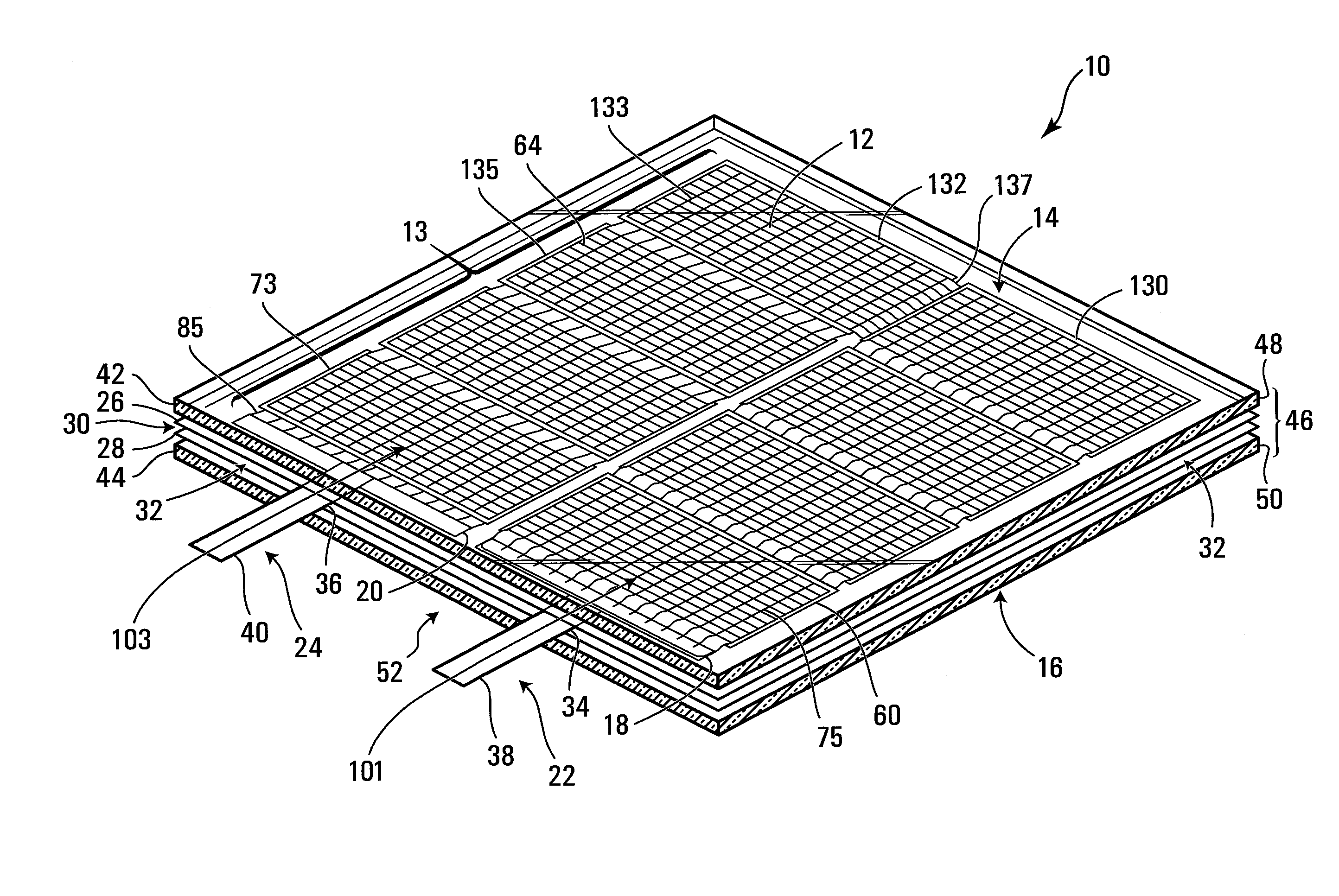
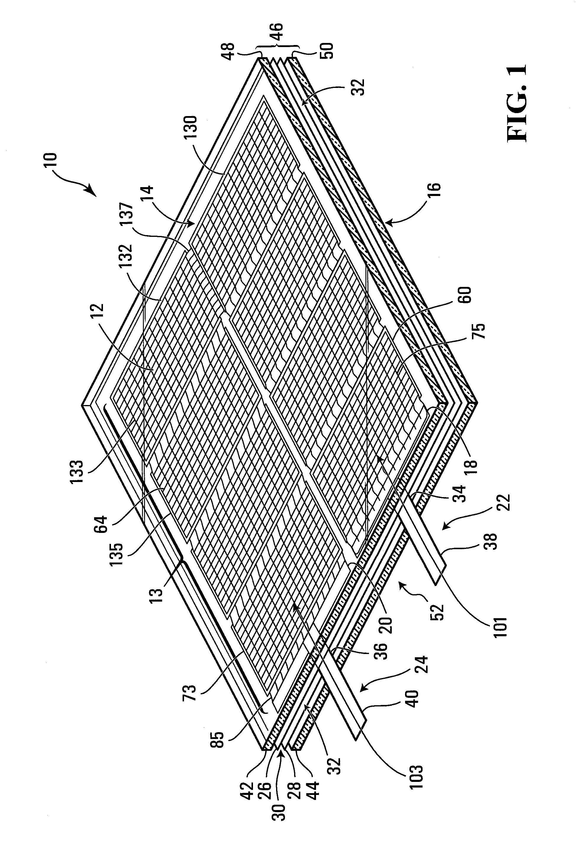
[0126]Referring to FIG. 1, a PV module apparatus according to a first embodiment of the invention is shown generally at 10. The apparatus 10 includes a plurality of PV cells shown generally at 12 arranged in a planar array 13 having a front side 14 and a back side 16. The PV cells are electrically connected together to form at least one string. In the embodiment shown the PV cells are connected together to form a string of 8 PV cells, having a positive terminal 18 and a negative terminal 20 for supplying electrical energy to a load. Positive and negative conductors 22 and 24 are connected to the positive and negative terminals 18 and 20 respectively. The apparatus further includes front and back encapsulating sheets 26 and 28 disposed on the front and back sides 14 and 16 respectively of the array 13 to form a sub-laminate 30 comprised of the array and the front and back encapsulating sheets. The sub-laminate 30 has a first outer perimeter edge 32 that extends all the way around the...


PUM

PropertyMeasurementUnit
temperatureaaaaaaaaaa
thicknessaaaaaaaaaa
thicknessaaaaaaaaaa

Abstract

A photovoltaic module apparatus includes PV cells arranged in a planar array, the PV cells being electrically connected in at least one string having positive and negative terminals. Positive and negative conductors are connected to the positive and negative terminals respectively and front and back encapsulating sheets are disposed on the front and back sides of the array to form a sub-laminate. Each of the positive and negative conductors has a respective portion extending from the positive and negative terminals, between the front and back encapsulating sheets. Front and back protectors are disposed on the front and back encapsulating sheets to form a laminate. First and second terminating portions of the positive and negative conductors extend outwardly from the outer perimeter edge of the laminate. A frame including a frame member having a holder may be provided about at least one portion of the outer perimeter edge of the laminate.

Description

BACKGROUND OF THE INVENTION[0001]This invention relates to photovoltaic (PV) modules and more particularly to configuring PV cells within a PV module to permit conductors associated with a string or strings of PV cells to extend from a perimeter edge of the PV module in which they are installed.[0002]The design and production of PV modules comprised of crystalline silicon PV cells has remained virtually unchanged for more than thirty years. A typical PV cell comprises semiconductor material with at least one p-n junction and front and back side surfaces having current collecting electrodes. When a conventional crystalline PV cell is illuminated, it generates an electric current of about 34 mA / cm2 at about 0.6-0.62V. A plurality of PV cells are typically electrically interconnected in series and / or in parallel strings to form a PV module that produces higher voltages and / or currents than a single PV cell.[0003]PV cells may be interconnected in strings by means of metallic tabs, made ...

Claims


Application Information

Patent Timeline
Patent Type & Authority Applications(United States)
IPC IPC(8): H01L31/048H01R13/60H01M6/00H01L31/042H02S30/10H02S40/34
CPCH01L31/02008H01L31/042Y02E10/50Y10T29/49108H02S40/34H01L31/0508H01L31/0512H02S20/00H01L31/02013H01L31/048H02S30/10H02S40/36H01L31/0488
Inventor RUBIN, LEONID BORISOVICHNEBUSOV, VALERY MICHAILOVICH
Owner DAY4 ENERGY
Why Eureka
Try Eureka