Calibration method for solar simulators usied in single junction and tandem junction solar cell testing apparatus

a solar simulator and testing apparatus technology, applied in the field of solar simulator calibration, can solve the problems of large equipment requirements, large equipment requirements, and large equipment requirements of stable state solar simulators

Inactive Publication Date: 2010-11-04
APPLIED MATERIALS INC
View PDF7 Cites 14 Cited by
  • Summary
  • Abstract
  • Description
  • Claims
  • Application Information

AI Technical Summary

Benefits of technology

[0036]In specific embodiments, an acceptable percentage difference between the measured intensity and the targeted intensity value in b) is about 1% or about 3%. In other specific embodiments, an acceptable percentage difference in monitoring module output short circuit current determined in step g) is about 2%, an acceptable percentage difference in monitoring module output open circuit voltage determined in step g) is about 2% and an acceptable percentage diffe

Problems solved by technology

The steady state solar simulator is a large, expensive device and at best has temporal instability (“flicker”) in the range of a few percent.
Although the light source used for simulation of AM0 sunlight for electrical tests of solar cells need not be an exact match at all wavelengths (which would be extremely difficult), it must produce the same effect on each individual junction as would AM0 sunlight.
As a result, very large-scale equipment is required, which is impractical.
Moreover, unless lighting is continued under the same conditions, the irradiance does not reach saturation and a great deal of time is required until measurement is started.
On the other hand, as the accumulated lighting time grows by long hours of lighting, the irradiance tends to decrease gradually and thus the irradiance characteristics are not stable.
Thus, the irradiation time required for the devices under testing depends on the operating speed of the shutter, and of

Method used


Image

  • Calibration method for solar simulators usied in single junction and tandem junction solar cell testing apparatus
  • Calibration method for solar simulators usied in single junction and tandem junction solar cell testing apparatus
  • Calibration method for solar simulators usied in single junction and tandem junction solar cell testing apparatus

Examples


Embodiment Construction

[0044]Embodiments of the present invention provide a solar cell testing apparatus and methods of calibrating a light source used to simulate the sun in the solar cell testing apparatus.

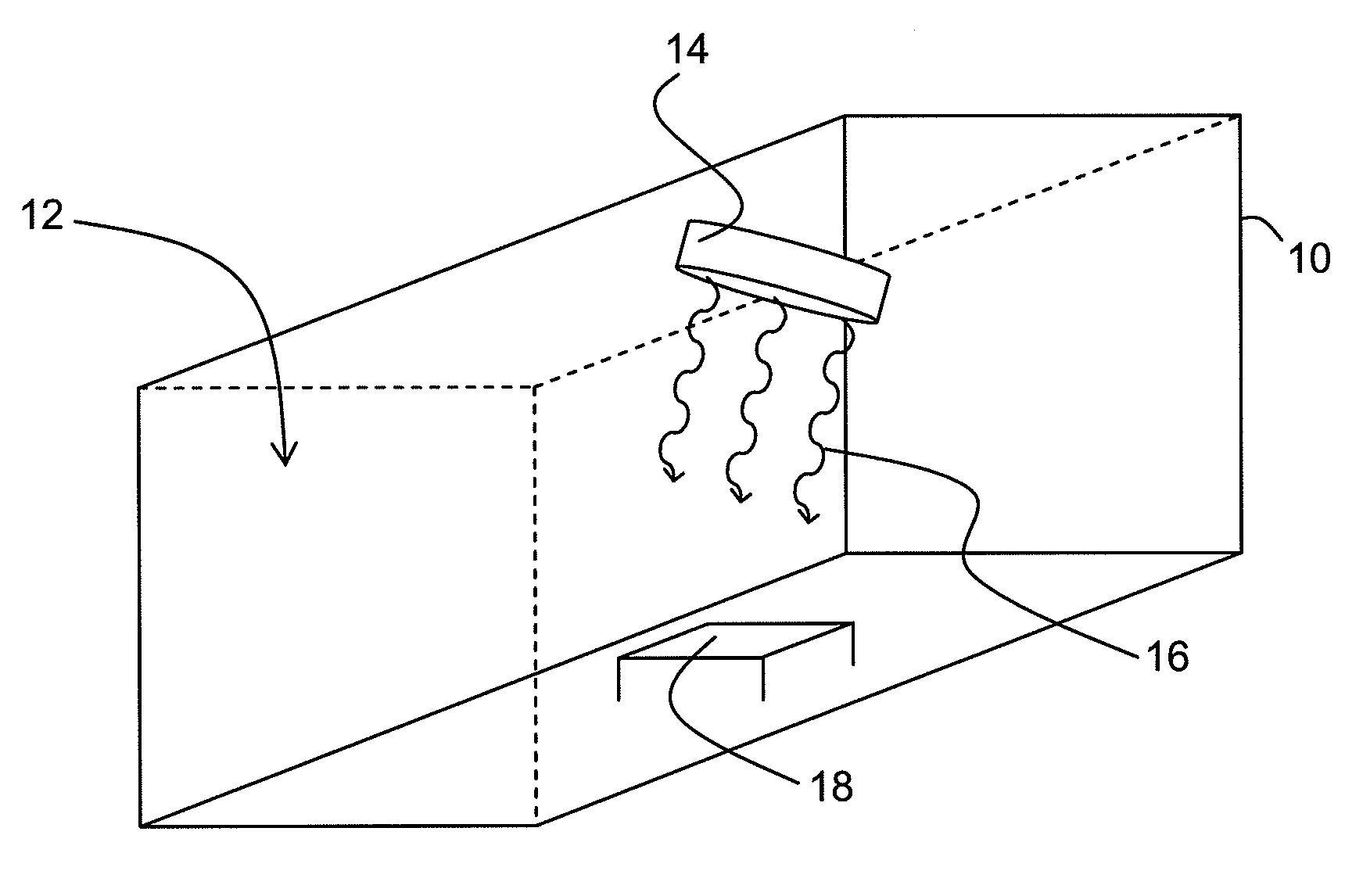
[0045]Equipment utilized in the inventive solar simulator calibration procedure will be discussed first. FIG. 1 depicts an exemplary embodiment of a solar cell testing apparatus 10, which can be of any appropriate size and configuration for testing a variety of differently sized modules. In the interior 12 of the apparatus 10, a light source 14 such as a lamp is present. The light source 14 serves as a solar simulator; it has the capacity of providing light 16 as intense as sunlight. The light source 14 may be physically attached to a wall of the apparatus 10, as shown, or freestanding in the interior 12 of the apparatus 10. Power can be supplied to the light source 14 through a variety of means as well known in the art. A substrate holder 18 is positioned inside the apparatus 10 so that the light 16 ...


PUM


Abstract

A method of calibrating a light source used to simulate the sun in solar cell testing apparatus. The method comprises using a control cell to measure the intensity of light from the light source at a first wavelength range as a function of output short circuit current, comparing the measured intensity to a targeted intensity value, optionally adjusting power to the light source until the measured intensity is substantially equal to the targeted intensity value, repeatedly using a calibrated monitoring module to periodically measure monitoring measured values for monitoring module output short circuit current, monitoring module output open circuit voltage and monitoring module quantum efficiency, obtaining average values for monitoring module output short circuit current, monitoring module output open circuit voltage and monitoring module quantum efficiency, comparing the measured values with the average values, and determining if differences in measured values and average values are within an acceptable limit.

Description

CROSS-REFERENCE TO RELATED APPLICATIONS[0001]This application claim priority under 35 U.S.C. §119(e) to U.S. Provisional Patent Application No. 61 / 175,109, filed May 4, 2009, the disclosure of which is hereby incorporated herein in its entirety.BACKGROUND OF THE INVENTION[0002]Embodiments of the present invention generally relate to devices used to test solar cells, and particularly to a procedure for calibrating a light source used to simulate the sun in a solar cell testing apparatus.DESCRIPTION OF THE RELATED ART[0003]Photovoltaic devices, such as solar cells, convert light into direct current electrical power. Thin film silicon solar cells typically are formed on a substrate and have one or more p-i-n junctions. Each p-i-n junction comprises a p-type layer, an intrinsic type layer, and an n-type layer that are amorphous, polycrystalline or microcrystalline materials. When the p-i-n junction of a solar cell is exposed to sunlight, consisting of energy from photons, the sunlight i...

Claims


Application Information

Patent Timeline
IPC IPC(8): G01J1/32
CPCG01J1/32G01J1/08
Inventor WANG, DAPENGFREI, MICHELSU, TZAY-FATANNER, DAVID
Owner APPLIED MATERIALS INC
Why Eureka
Try Eureka