
Cold-shrinkable type rubber insulation sleeve and method of manufacturing

a rubber insulation and cold-shrinkable technology, applied in the direction of insulating bodies, insulated conductors, cables, etc., can solve the problems of increased manufacturing costs, undesirable shape and quality, and difficulty in molding the external semi-conductive layer b>7/b>, and achieve the effect of cheaper and more effectiv

Inactive Publication Date: 2010-11-04
FURUKAWA ELECTRIC CO LTD
View PDF12 Cites 1 Cited by
  • Summary
  • Abstract
  • Description
  • Claims
  • Application Information

AI Technical Summary

Benefits of technology

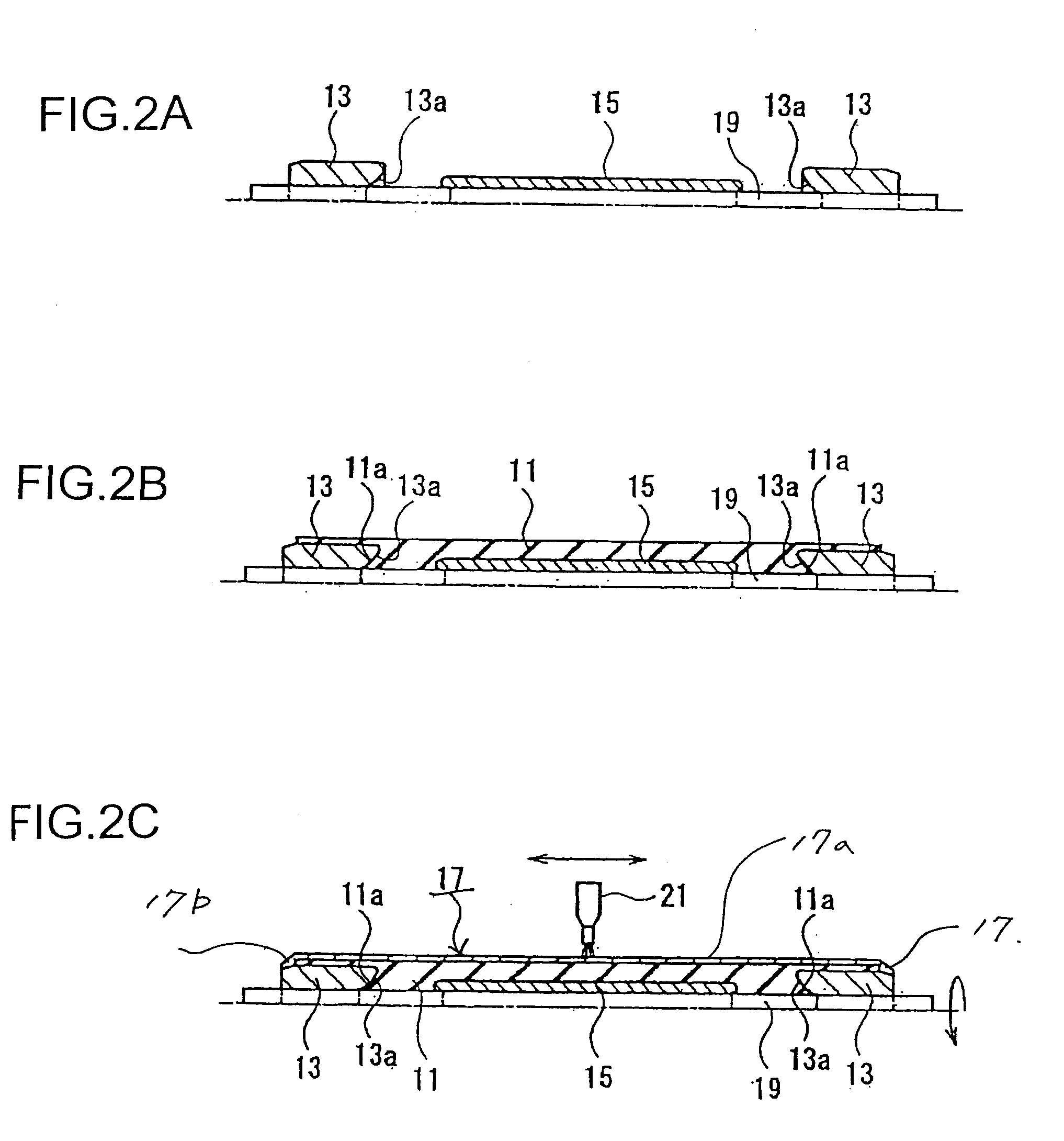
The present invention provides a cheaper and more effective method for making a cold-shrinkable type rubber insulation sleeve. The sleeve includes a reinforced insulation sleeve, semiconductive stress-relief cones, an internal semiconductive layer, and an external semiconductive layer. The reinforced insulation sleeve is made by injecting an elastic material into a mold. The semiconductive stress-relief cones are made by injecting a semiconductive rubber material into another mold. The internal semiconductive layer is arranged around a cylindrical core. The semiconductive stress-relief cones are arranged at each side of the internal semiconductive layer with a gap between them. The reinforced insulation sleeve covers the internal semiconductive layer and both semiconductive stress-relief cones. The coating is formed by spray coating a liquid semiconductive rubber material and drying and vulcanizing it to form an external semiconductive layer. The invention provides a cost-effective and efficient method for making a cold-shrinkable type rubber insulation sleeve.

Problems solved by technology

On the other hand, the method has a disadvantage that it is difficult to mold the external semiconductive layer 7 and the semiconductive stress-relief cone 3 with a desirable shape and quality.
However, this method has a disadvantage that manufacturing cost increases due to the increased number of the mold.
Moreover, in both the methods, there is a problem that the thickness of the external semiconductive layer 7 may vary.
Molding sometimes causes an unbalance in the flow of the injected semiconductive rubber material inside the mold because of presence of the parts in which the rubber material does not flow well.
This causes inefficiency in manufacturing because more time is required for molding and curing.
This also causes increased manufacturing cost because the mold for the external semiconductive layer 7 becomes larger than the mold for the reinforced insulation sleeve 1, and because, if the thickness of the external semiconductive layer 7 is to be made thick, a mold and a press even larger and more expensive are required.

Method used


Image

  • Cold-shrinkable type rubber insulation sleeve and method of manufacturing
  • Cold-shrinkable type rubber insulation sleeve and method of manufacturing
  • Cold-shrinkable type rubber insulation sleeve and method of manufacturing

Examples


Embodiment Construction

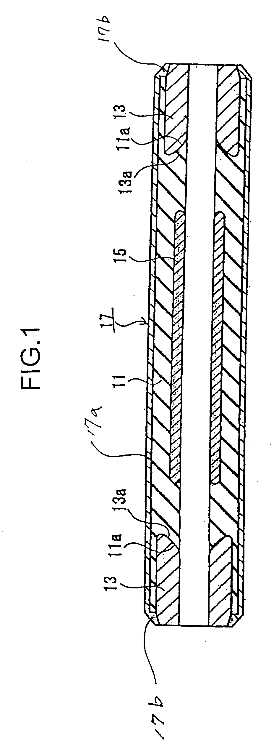
[0024]Exemplary embodiments of the present invention are explained with reference to the accompanying drawings. FIG. 1 is a cross-section of a cold-shrinkable type rubber insulation sleeve according to the present invention.

[0025]The cold-shrinkable type rubber insulation sleeve is formed into one piece mainly with rubber materials such as Ethylene-Propylene Rubber (EPR) and Silicone Rubber (SR) that are elastic at room temperature. The cold-shrinkable type rubber insulation sleeve includes a reinforced insulation sleeve 11, a semiconductive stress-relief cone 13 at each end of the reinforced insulation sleeve 11, an internal semiconductive layer 15 that is arranged on the inner surface of the reinforced insulation sleeve 11, and an external semiconductive layer 17 that is arranged around the reinforced insulation sleeve 11 to cover the outer surface.

[0026]The reinforced insulation sleeve 11 is molded with the rubber material such as Ethylene-Propylene into a tube shape that has a s...


PUM

PropertyMeasurementUnit
thicknessaaaaaaaaaa
thicknessaaaaaaaaaa
semiconductiveaaaaaaaaaa

Abstract

A cold-shrinkable type rubber insulation sleeve includes a reinforced insulation sleeve, a semiconductive stress-relief cone, an internal semiconductive layer, and an external semiconductive layer. The reinforced insulation sleeve, the semiconductive stress-relief cone, and the internal semiconductive layer are formed by molding, and the external semiconductive layer is formed by coating.

Description

CROSS-REFERENCE TO RELATED APPLICATIONS[0001]The present application is a continuation of and claims the benefit of priority under 35 U.S.C. §120 from U.S. application Ser. No. 11 / 589,108, filed Oct. 30, 2006, which is incorporated herein by reference in its entirety. U.S. application Ser. No. 11 / 589,108 is a divisional application of U.S. application Ser. No. 10 / 868,843, filed Jun. 16, 2004, which is based upon and claims the benefit of priority under U.S.C. §119 from prior Japanese Patent Application No. 2003-174,964, filed Jun. 19, 2003.BACKGROUND OF THE INVENTION[0002]1) Field of the Invention[0003]The present invention relates to a cold-shrinkable type rubber insulation sleeve that is used for a joint of power cables such as high-voltage CV (cross-linked polyethylene insulated vinyl sheath) cables.[0004]2) Description of the Related Art[0005]There are various kinds of structures for insulation joints for high-voltage CV cables. Such structures include an extrusion molded type, ...

Claims


Application Information

Patent Timeline
Patent Type & Authority Applications(United States)
IPC IPC(8): B29C45/16H02G1/14H02G15/08H01B17/64H02G15/103H02G15/18H02G15/184H02G15/196
CPCH02G15/103Y10T428/1328Y10T428/1393H02G15/184H01B7/0208H02G15/196
Inventor KOBAYASHI, SHOZOKURITA, KOZOTAKAOKA, ISAO
Owner FURUKAWA ELECTRIC CO LTD
Learn More