
System and method for determining the temperature of a permanent magnet in a machine

Active Publication Date: 2010-11-04
GENERAL ELECTRIC CO
View PDF4 Cites 37 Cited by
  • Summary
  • Abstract
  • Description
  • Claims
  • Application Information

AI Technical Summary

Benefits of technology

[0006]Aspects and advantages of the invention are set forth below in the following description, or may be obvious from the description, or may be learned through practice of the invention.

Problems solved by technology

Operation of the machine creates losses and then subsequent heating in the permanent magnet.
For a given operating point and design, the permanent magnet has an effective maximum allowable operating temperature, which, if exceeded by even a few degrees for a short period of time, may result in sudden and irreversible demagnetization of the permanent magnet which prevents the machine from operating at its designed potential.
This risk can be particularly acute during the event of a sudden short circuit fault of the generator or seen by the generator, for example, a short circuit in the windings, terminals, or cabling, or more commonly, of the generator control electronics such as a rectifier or power electronic converter.
Directly monitoring the permanent magnet temperature is not feasible because of the rotation of the rotor.
Therefore, control systems are typically limited to, at best, indirectly monitoring the permanent magnet temperature by monitoring the temperature of the stator windings.
This arrangement, however, is also susceptible to failure of the RTDs or wiring.
Furthermore, with only stator winding temperature detection, there is no direct knowledge of the magnet temperature or guarantee that the magnet temperature is within safe or desired bounds.
Therefore, controlling the load on the machine based on the stator temperature may unnecessarily limit the rated load of the machine or put the magnets at unacceptable risk of irreversible demagnetization.

Method used


Image

  • System and method for determining the temperature of a permanent magnet in a machine
  • System and method for determining the temperature of a permanent magnet in a machine
  • System and method for determining the temperature of a permanent magnet in a machine

Examples


Embodiment Construction

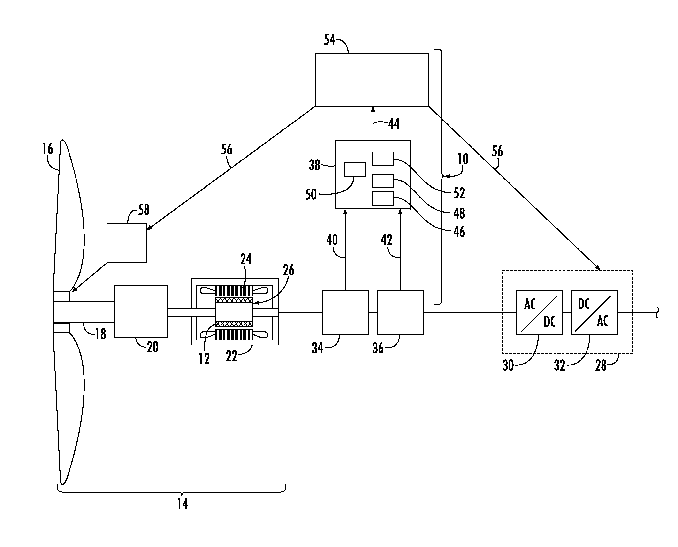
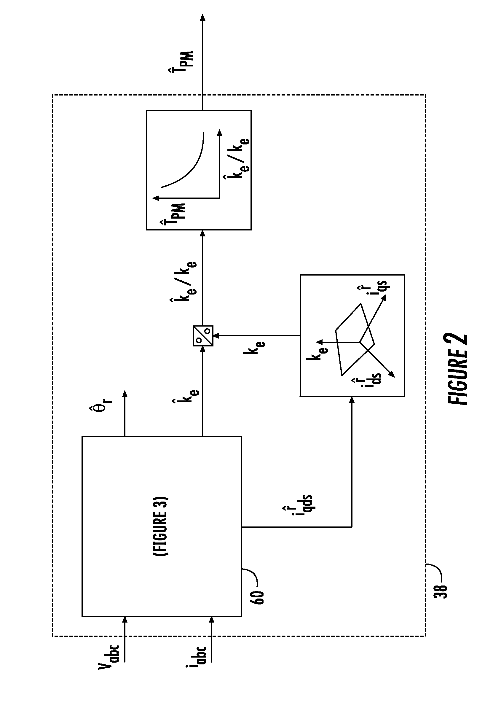
[0015]Reference will now be made in detail to present embodiments of the invention, one or more examples of which are illustrated in the accompanying drawings. The detailed description uses numerical and letter designations to refer to features in the drawings. Like or similar designations in the drawings and description have been used to refer to like or similar parts of the invention.

[0016]Each example is provided by way of explanation of the invention, not limitation of the invention. In fact, it will be apparent to those skilled in the art that modifications and variations can be made in the present invention without departing from the scope or spirit thereof. For instance, features illustrated or described as part of one embodiment may be used on another embodiment to yield a still further embodiment. Thus, it is intended that the present invention covers such modifications and variations as come within the scope of the appended claims and their equivalents.

[0017]Embodiments of...


PUM


Abstract

A system for determining a temperature of a permanent magnet in a machine includes a voltage sensor that generates a voltage signal reflective of a stator voltage and a current sensor that generates a current signal reflective of a stator current. A processor receives the voltage and current signals and generates a temperature signal reflective of the temperature of the permanent magnet in the machine. A method for controlling a load of a machine includes generating a voltage signal, a current signal, and a temperature signal reflective of the temperature of a permanent magnet in the machine. The method further includes adjusting the load of the machine based on the temperature signal.

Description

FIELD OF THE INVENTION[0001]The present invention pertains to a permanent magnet in a machine. Specifically, embodiments of the present invention involve a system and method for determining the temperature of a permanent magnet in a generator or motor.BACKGROUND OF THE INVENTION[0002]Machines such as motors and generators typically include a rotor and a stator. The rotor may include a permanent magnet that produces a magnetic field. In a generator, rotation of the rotor with respect to the stator causes the magnetic field from the permanent magnet to rotate, thereby inducing electric current flow through windings in the stator. Conversely, in a motor, current flow through the stator windings induces rotation of the permanent magnet, and thus the rotor.[0003]Operation of the machine creates losses and then subsequent heating in the permanent magnet. For a given operating point and design, the permanent magnet has an effective maximum allowable operating temperature, which, if exceede...

Claims


Application Information

Patent Timeline
IPC IPC(8): H02P9/04H02P7/285
CPCH02P29/0044G01K7/42G01K13/08G01K2217/00H02P29/60
Inventor JANSEN, PATRICK LEE
Owner GENERAL ELECTRIC CO
Learn More