
Apparatus and Method for Reducing Contamination of Surgical Sites

a technology for surgical sites and masks, applied in the field of surgical instruments, can solve the problems of reducing the availability of hospital beds for other patients, dramatic increase in patient length of stay and cost, and hospital acquired infections (“hai”), so as to prevent bacterial invasion, the effect of being effective, inexpensive and easy to implemen

Active Publication Date: 2010-11-04
MIZUHO ORTHOPEDIC SYST
View PDF19 Cites 14 Cited by
  • Summary
  • Abstract
  • Description
  • Claims
  • Application Information

AI Technical Summary

Benefits of technology

[0016]The present invention is directed to the root cause of the SSI problem: effectively preventing bacterial invasion of a surgically created wound during the surgery; and is also directed to the second part of the problem: making the solution effective, inexpensive and easy to implem

Problems solved by technology

Hospital-acquired infections (“HAI”), also known as nosocomial infections, are a significant problem in modern healthcare systems.
HAI dramatically increases patient length of stay and cost and decreases hospital bed availability for other patients.
If these bacteria gain access to a normally sterile space, such as in the capsule of a joint, they may multiply without resistance and create a huge infectious burden on the host.
Bacteria protected within biofilms are much harder to kill than individual isolated bacteria.
SSI from bacterial invasion is particularly deleterious in procedures such as orthopedic joint arthroplasty, cardiovascular surgery, and neurosurgery.
These types of infections develop deep within the body, are difficult to treat, and are devastating to patients.
Antibiotics can't always penetrate tissues to reach bacteria that have taken root on implanted materials, and revision surgery on the infected joint is often necessary to eradicate the infection.
Sometimes the infection will have caused so much bone loss that a second prosthesis replacement isn't an option, in which case the only option is fusing the bones together leaving the joint stiff and immobile and the patient in need of a mobility aid.
However, the ability of LFORs to accomplish this and prevent infections is qualified and debatable.

Method used


Image

  • Apparatus and Method for Reducing Contamination of Surgical Sites
  • Apparatus and Method for Reducing Contamination of Surgical Sites
  • Apparatus and Method for Reducing Contamination of Surgical Sites

Examples


example 1

FLOW SIMULATION EXAMPLE 1

Prior Art—Flow Not Horizontally Level with the Surface and Not Sterile.

[0099]Referring to FIGS. 17-19, a series of flow simulations are depicted that employ an emitter configuration of the type described in the article by Thore M, et al.: Further bacteriological evaluation of the TOUL mobile system delivering ultra-clean air over surgical patients and instruments, JOURNAL OF HOSPITAL INFECTION 63, 185-192 (2006), noted above as similar to U.S. Pat. No. 3,820,536, configured and deployed as described in that article and employing flow velocities described in that article. The emitter outlet size is 0.55 meters (21.654 inches) wide, 0.4 meters (13.638 inches) high and has a central airflow zone with a peripheral airflow zone 1.5 inches inset from the edges of the emitter. The peripheral zone is angled outwardly 25 degrees. The emitter is 0.681 meters (24.350 inches) above surface 102 and is inclined toward surface 102 at a 60-degree angle. The arcuate surface ...

examples 2-6

FLOW SIMULATION EXAMPLES 2-6

Introductory Comments

[0102]In Flow Simulation Examples 2-6 and corresponding FIGS. 20-34, the flow simulations used the same nominal emitter flow velocity (350 ft / min), so a higher series 135-139 of reference numerals indicative of higher flow velocities are employed in FIGS. 20-34 to supplement the convention of weighted solid lines and dashed lines for illustrating velocities. Nominal ranges of velocities for solid and dashed lines are indicated in FIGS. 20-34 by reference numbers as follows:

Reference numeralVelocity (ft / min.)135from about 280 to about 350136from about 220 to about 280137from about 140 to about 220138from about 80 to about 140139from about 20 to about 80

The same reference numeral is used for a given range of velocities whether the reference numeral leads to a solid line or a dashed line. Solid flow lines at a velocity of 135 have a heavier weight than solid flow lines at a velocity of 136, solid flow lines at a velocity of 136 have a he...

example 2

FLOW SIMULATION EXAMPLE 2

Prior Art—Coanda Jet Effect, Flow Horizontal But Not Sterile

[0103]Referring to FIGS. 20-22, a series of flow simulations are depicted that employ a rectilinear flat bottomed emitter 115 that is 8 inches wide and 0.5 inches high (the dimensions of the flat nozzles depicted in U.S. Pat. No. 4,275,719 to Mayer, mentioned above) over a flat plate 202, as in a Coanda Effect for a jet emitted adjacent a flat surface. A space of 0.375 above the flat plate was necessary for simulation stability. The simulations were performed using the same computer program as in Flow Simulation Example 1. The following parameters were used for the program simulations: velocity condition at emitter outlet (exiting emitter) was 350 ft / min; all other boundaries received P=0 (atmospheric) conditions. Mesh size was 16″ wide, 12″ tall and 24″ long. The simulation contained 190,490 fluid elements and converged after 904 iterations

[0104]FIG. 20 is an isometric depiction of the flow trace e...


PUM


Abstract

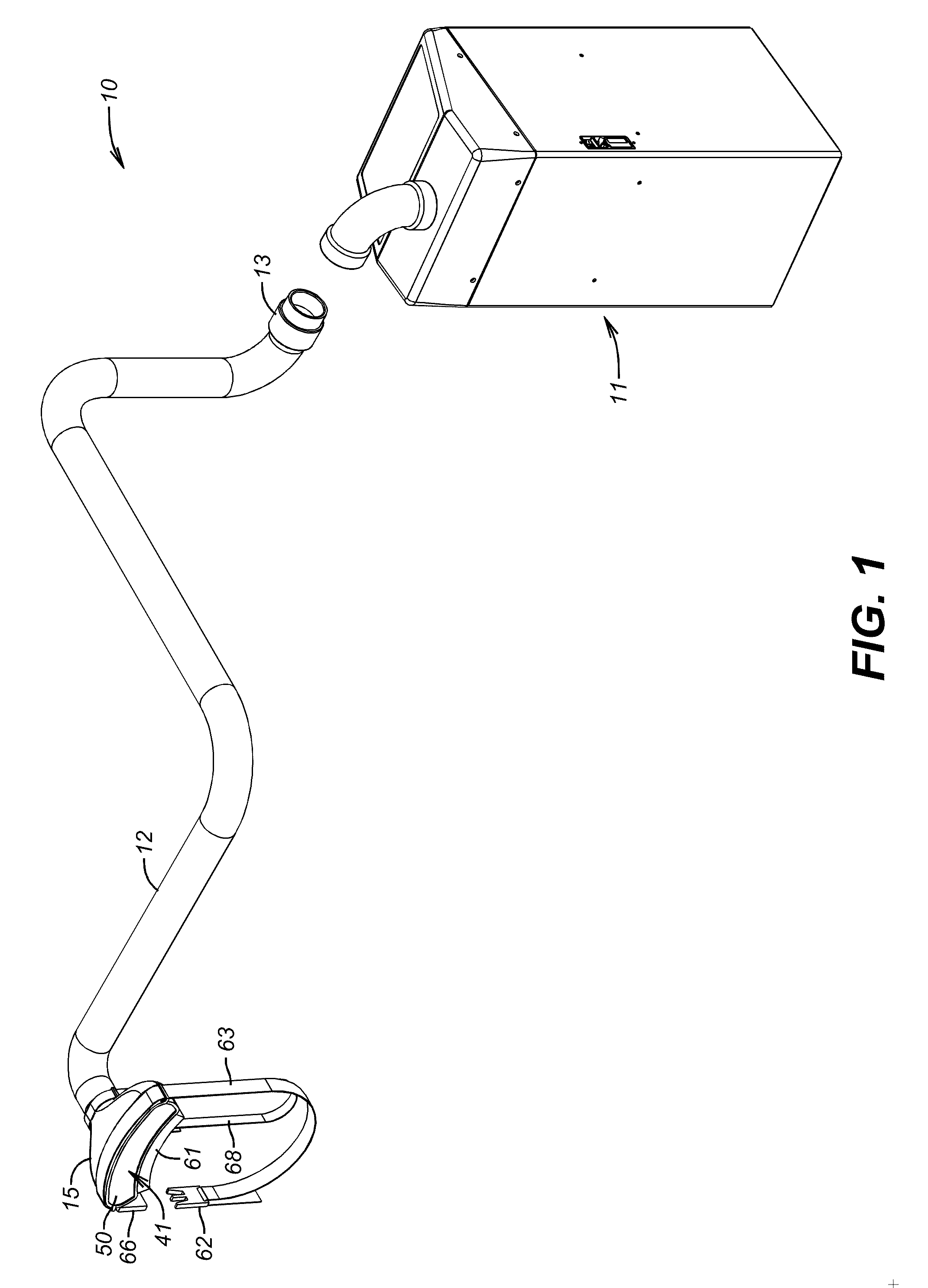
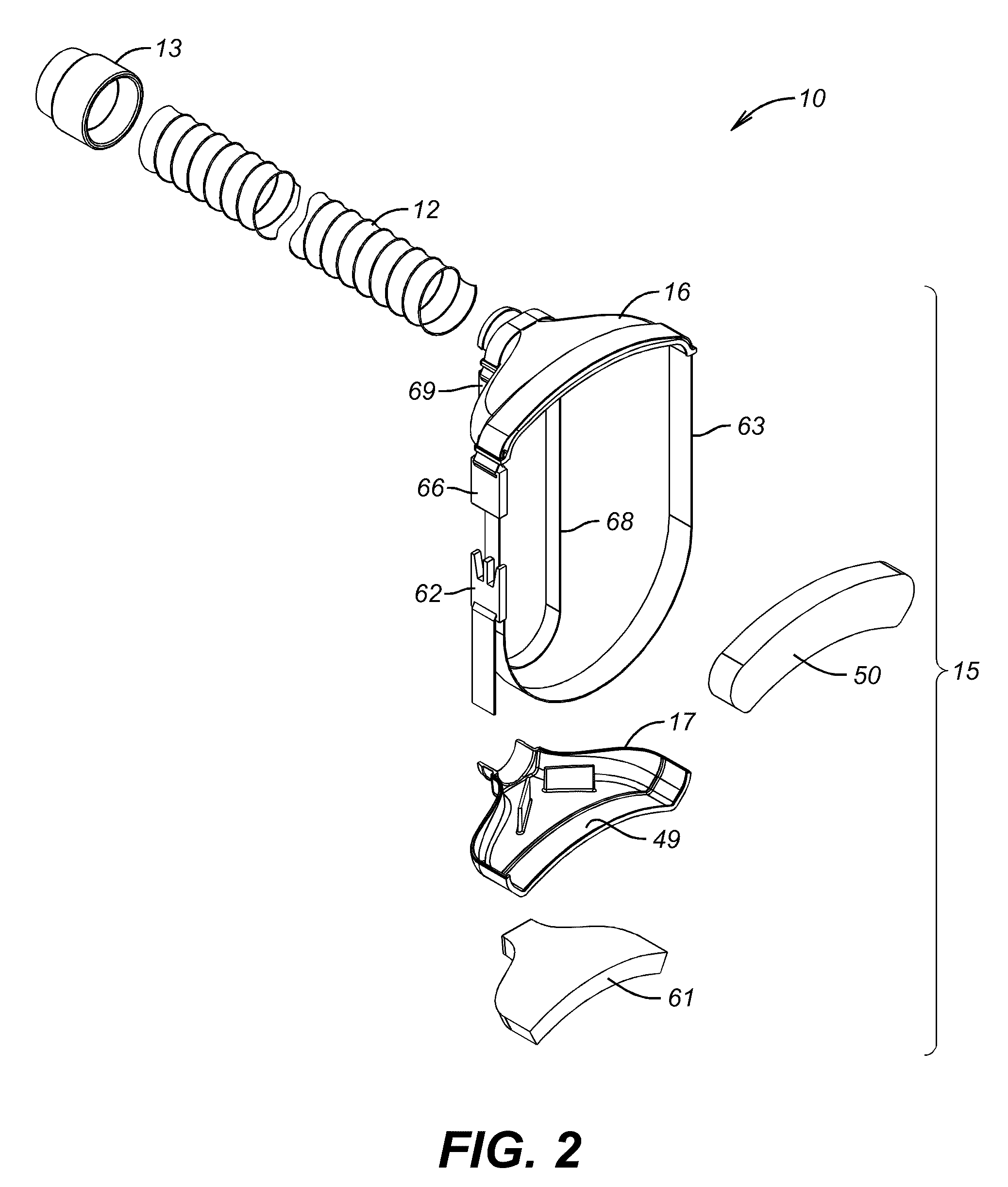
Apparatus and methods for protecting a patient from surgical site infection from airborne microbes during surgery. A sterile gas flow conditioning emitter for affixation onto an anatomical surface of a patient adjacent a site of incision is anatomically shape conforming for attaching a unidirectional coherent non-turbulent flow field of sterile gas substantially anatomically levelly on that anatomical surface and flowing the flow field in the direction of that site while essentially preventing ambient airborne particles from entering the interior of the flow field under the emitter to maintain the gas essentially sterile during passage over the site.

Description

CROSS-REFERENCE TO RELATED APPLICATIONS[0001]Not ApplicableSTATEMENT REGARDING FEDERALLY SPONSORED RESEARCH OR DEVELOPMENT[0002]Not ApplicableBACKGROUND OF THE DISCLOSURE[0003]1. Field of the Disclosure[0004]This invention relates to surgery, and more particularly, to air barriers used to reduce contamination of surgical sites.[0005]2. Background Art[0006]Hospital-acquired infections (“HAI”), also known as nosocomial infections, are a significant problem in modern healthcare systems. In 2002, approximately 1.8 million people contracted an HAI in U.S. healthcare facilities, and approximately 100,000 died as a result. HAI dramatically increases patient length of stay and cost and decreases hospital bed availability for other patients. The second most prolific cause of HAI is surgical site infections (“SSI”), which account for about 22% of all nosocomial infections. Hollenbeak C S, et al., The clinical and economic impact of deep chest surgical site infections following coronary artery...

Claims


Application Information

Patent Timeline
IPC IPC(8): A61B19/08A61M37/00
CPCA61B19/38A61M13/003A61G13/108A61B2019/385A61B90/40A61B2090/401
Inventor SELF, SEAN D.MARCEK, GEOFF A.FOWLER, JR., JAMES M.
Owner MIZUHO ORTHOPEDIC SYST
Learn More