Supercharge Your Innovation With Domain-Expert AI Agents!

Forming machine for forming meandering loop winding and method of forming meandering loop winding

a technology of winding and winding loop, which is applied in the manufacture of stator/rotor bodies, magnets, magnetic bodies, etc., can solve the problems of difficult to enhance the winding occupation factor between adjacent teeth, difficult to suppress an increase in the number of components required to constitute stators, and high labor costs, so as to achieve efficient manufacturing of loops

Inactive Publication Date: 2010-11-11
TOYO SEIKAN GRP HLDG LTD
View PDF8 Cites 2 Cited by
  • Summary
  • Abstract
  • Description
  • Claims
  • Application Information

AI Technical Summary

Benefits of technology

[0010]Accordingly, it is an object of the present invention to provide a forming machine for efficiently manufacturing a loop winding having a plurality of meandering parts.
[0011]It is another object of the present invention to provide a method of forming a meandering loop winding, for efficiently manufacturing a loop winding having a plurality of meandering parts.
[0013]According to this configuration, the first and second die units are each provided with the winding diameter reducing means for reducing the loop winding in the radial direction according to the displacement of the first die unit in the axial direction in forming the meandering loop winding; therefore, it is possible to largely reduce the elongation of the loop winding during forming of the meandering parts in the loop winding, and to remarkably enhance the productivity in the press forming.
[0016]With the radii of curvature of the holding surfaces of the winding holding parts thus set appropriately, it is possible to securely hold the loop winding, without exerting any irrational stress on the loop winding which is varied in diameter through the process of press forming (working).
[0018]Since the roller rolling surface of each of the first and second roller guides constituting the winding diameter reducing means is formed to be a curved surface, the first and second rollers roll on the curved surface shaped roller rolling surfaces of the first and second roller guides according to the displacement in the axial direction of the first die unit. Therefore, it is possible to reduce the winding diameter according to the extent of working of the loop winding, and to form the plurality of meandering parts without exerting any irrational stress on the loop winding.
[0020]According to this configuration, it is possible to form the plurality of meandering parts in the loop winding and simultaneously to reduce the loop winding in the radial direction, by the press forming step. Therefore, it is possible to efficiently form the loop winding having a plurality of meandering parts, without exerting any irrational stress on the loop winding.

Problems solved by technology

Therefore, it is difficult to suppress an increase in the number of component parts required to constitute the stator, and much labor is needed for winding the respective windings for the three phases.
Moreover, in the stator having the windings on the wave winding mode, it is difficult to enhance the winding occupation factor between the adjacent teeth.
Further, it is difficult to reduce the size in the axial direction of the motor by reducing the height at the coil end, in order to enhance the mountability onto a vehicle or the like.
However, such a loop winding having meandering parts was not generally used in the past, and, therefore, establishment of a method for forming such a meandering loop winding is being desired.

Method used


Image

  • Forming machine for forming meandering loop winding and method of forming meandering loop winding
  • Forming machine for forming meandering loop winding and method of forming meandering loop winding
  • Forming machine for forming meandering loop winding and method of forming meandering loop winding

Examples


Embodiment Construction

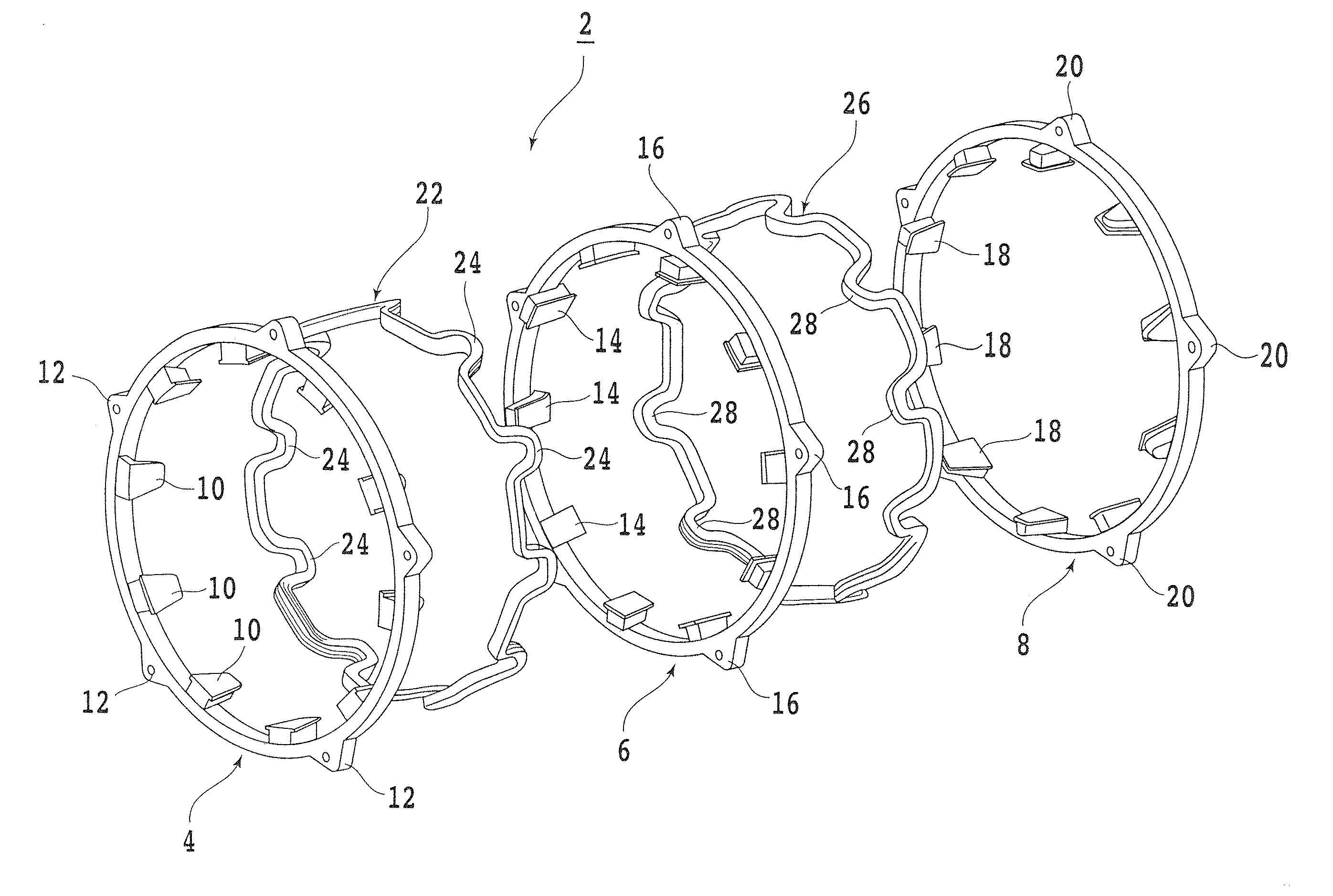
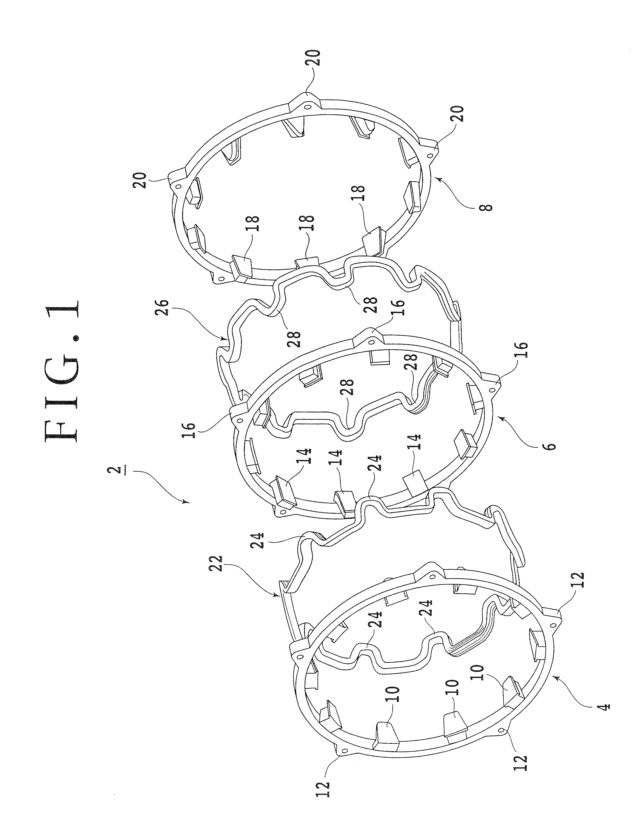
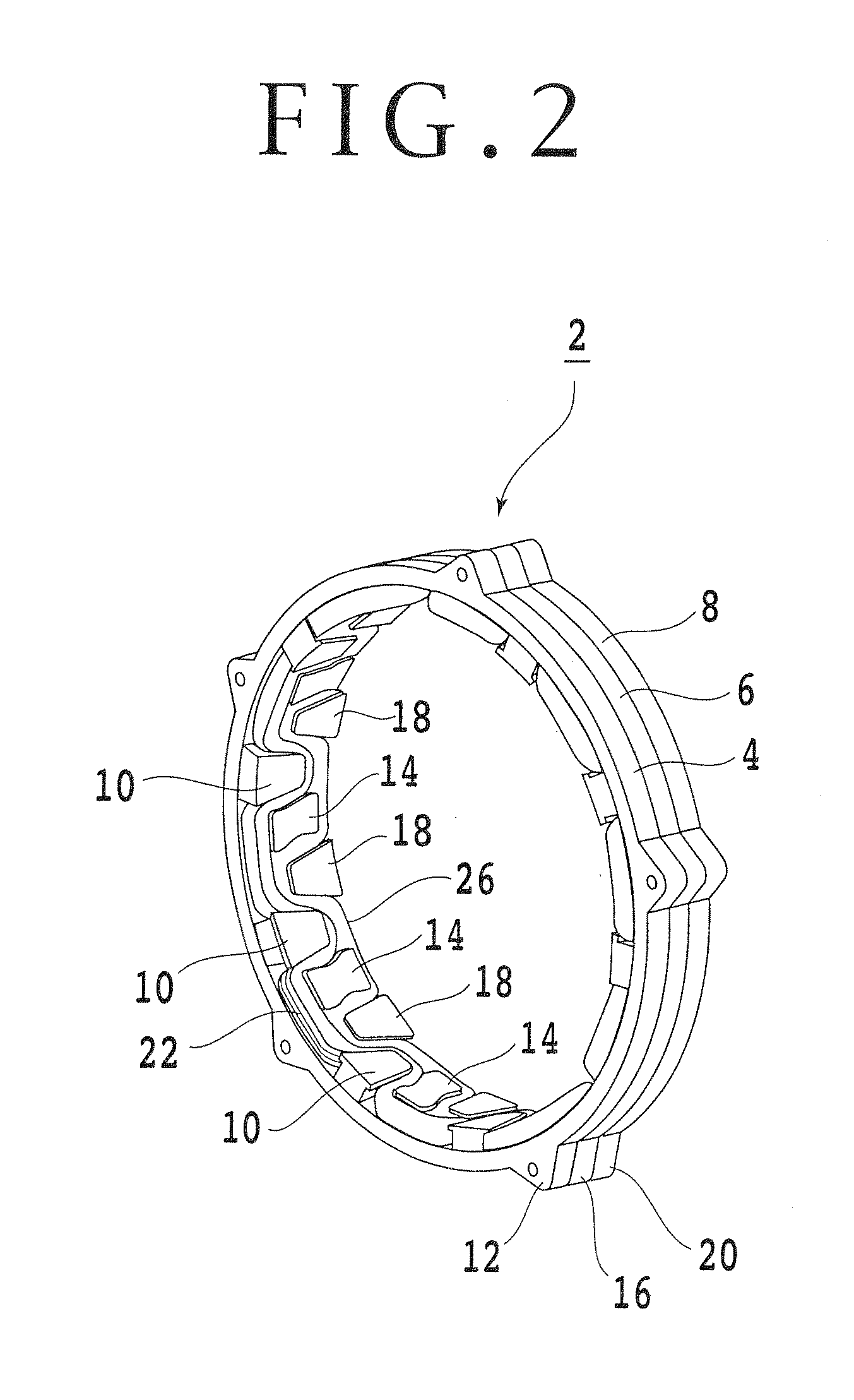
[0040]Now, preferred embodiments of the present invention will be described in detail below referring to the drawings. First, before describing a forming machine for forming a meandering loop winding according to an embodiment of the present invention, a stator in which a loop winding formed by the forming machine based on the present invention is mounted will be described referring to FIGS. 1 to 3. This annular stator 2 constitutes, for example, a permanent magnet type alternating current synchronous motor (also called a brushless DC motor or a claw pole type motor) to be mounted on a hybrid powered vehicle as a vehicle drive source together with an engine. For example, in a parallel hybrid powered vehicle with a structure in which an engine, a claw pole type motor and a transmission are connected in series, the drive force of at least either one of the engine and the claw pole type motor is transmitted through the transmission to drive wheels of the vehicle.

[0041]In addition, when...


PUM

PropertyMeasurementUnit
electrical angleaaaaaaaaaa

Abstract

A method for forming a loop winding having a plurality of meandering parts and disposed in a stator of a motor which includes: disposing the loop winding between a first die unit having a plurality of first dies and a second die unit having a plurality of second dies; and press forming the loop winding between the first dies and the second dies by relatively moving the first die unit and the second die unit toward each other, wherein the press forming step is so performed as to provide the loop winding with a plurality of meandering parts and, simultaneously, to reduce the loop winding in the radial direction.

Description

CROSS-REFERENCE TO RELATED APPLICATIONS[0001]This is a Divisional Application which claims the benefit of pending U.S. patent application Ser. No. 11 / 878,767, filed on Jul. 26, 2007, and claims priority of Japanese Patent Application No. 2006-204510, filed on Jul. 27, 2006, and Japanese Patent Application No. 2007-119376, filed on Apr. 27, 2007. The disclosures of the prior applications are hereby incorporated herein in their entirety by reference.BACKGROUND OF THE INVENTION[0002]1. Field of the Invention[0003]The present invention relates to a forming machine for forming a meandering loop winding used as a stator winding in a motor and to a method of forming the meandering loop winding.[0004]2. Description of the Related Art[0005]As a hybrid powered vehicle motor or an electric vehicle motor, the permanent magnet type alternating current synchronous motor or brushless DC motor in which permanent magnets are used in a rotor is widely used. As one of this type of motors, a permanent ...

Claims


Application Information

Patent Timeline
Patent Type & Authority Applications(United States)
IPC IPC(8): H01F7/06
CPCH01F41/065H01F41/0687H02K3/18H02K15/0485Y10T29/49078Y10T29/53143Y10T29/49071Y10T29/53157Y10T29/53148Y10T29/49073Y10T29/49012Y10T29/49009Y10T29/532Y10T29/49011H01F41/071H01F41/098
Inventor TAKIZAWA, DAIJIROKATOH, HISASHITAKEASHI, TADANOBUMORISHITA, SUNAOOOHORI, KEI
Owner TOYO SEIKAN GRP HLDG LTD
Features
  • R&D
  • Intellectual Property
  • Life Sciences
  • Materials
  • Tech Scout
  • Unparalleled Data Quality
  • Higher Quality Content
  • 60% Fewer Hallucinations
Learn More