Waterproof ceiling with multiple types of structures

Active Publication Date: 2010-11-11
KIM WON KEOL
View PDF3 Cites 4 Cited by
  • Summary
  • Abstract
  • Description
  • Claims
  • Application Information

AI Technical Summary

Benefits of technology

[0026]As described above, the present invention provides a waterproof ceiling with multiple types of structures, which is manufactured by assembling standardized parts, thus allowing a single-layered or multi-layered structure to be easily installed, allowing a broken part to be easily replaced with a new one, therefore reducing maintenance costs, and allowing equipment such as a pipe, wire, duct or tray to be arranged without regard to spatial restrictions

Problems solved by technology

Water leakage from a ceiling causes fatal damage to main equipment (server, precision equipment, medical equipment, electronic devices, etc.) and power equipment, and leads to secondary damage such as the loss of information resources, thus resulting in vast damage to property.
Thus, when water leaks from the water pipes in the ceiling of the same floor or an upper floor, the water may cause serious damage to equipment installed under the water pipes.
This accident led to property damage which amounted to several tens of billions of won and the interruption of security exchange services.
As is known from the example, the leakage of water or the malfunction of equipment can cause serious trouble related to information which is the main resource of an information society and the function of a building, for example, the server of a computer room, the computerized information of a bank, the power equipment of a building, and expensive medical equipment, thus causing damage to customers, members, and consumers.
However, conducting the work is in most cases impossible because there are few cases where the upper floor is empty.
Although waterproofing is possible, it is substantially impossible to prevent the leakage of water to a fan coil pipe,

Method used


Image

  • Waterproof ceiling with multiple types of structures
  • Waterproof ceiling with multiple types of structures
  • Waterproof ceiling with multiple types of structures

Examples


Embodiment Construction

[0044]The above and other objects, features and advantages of the present invention will be more clearly understood from the following detailed description taken in conjunction with the accompanying drawings. Hereinafter, waterproof ceiling with multiple types of structures according to various embodiments of the present invention will be described in detail with reference to the accompanying drawings. The terminologies used in the description and the claims of the present invention are widely used in the field of a construction material, and will be described in detail when necessary.

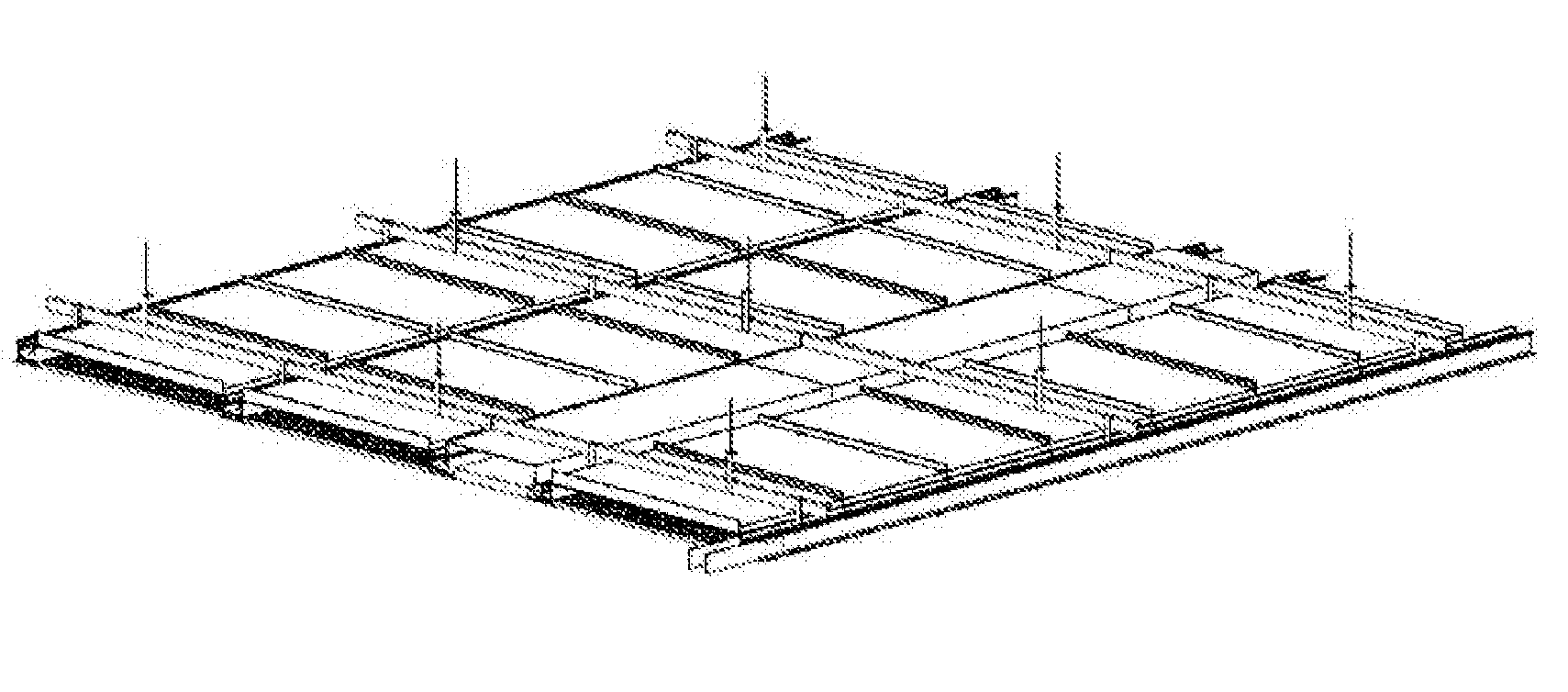
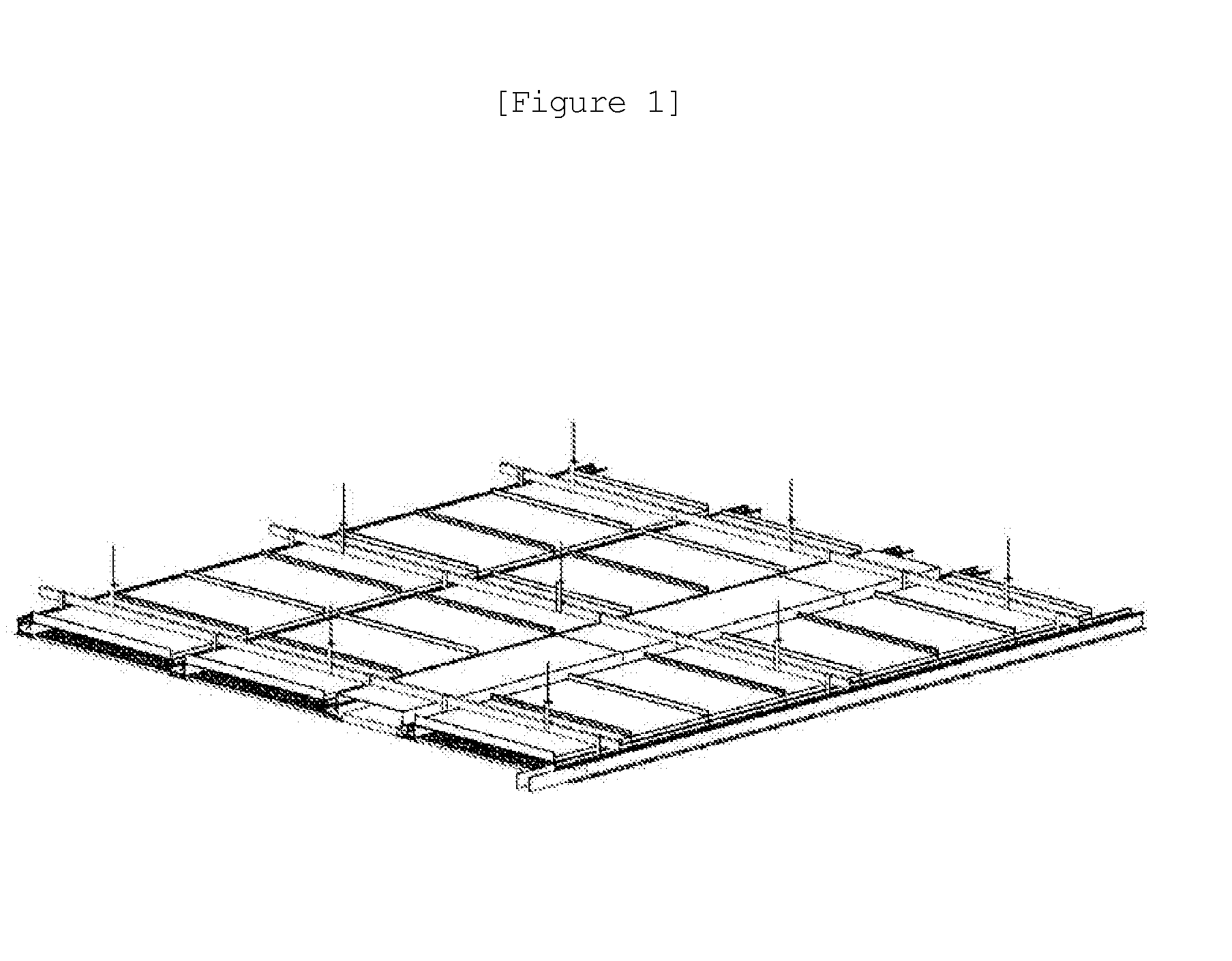
[0045]FIG. 1 is a perspective view illustrating a standard-type waterproof ceiling, which is one embodiment of a waterproof ceiling with multiple types of structures according to the present invention, FIG. 2 is a partial bottom perspective view illustrating the standard-type waterproof ceiling, and FIG. 3 is a partial top perspective view illustrating the standard-type waterproof ceiling. Further, FIG...


PUM


Abstract

Disclosed herein is a waterproof ceiling with multiple types of structures. The waterproof ceiling includes a hanger unit secured at an upper end thereof to a ceiling wall or the waterproof ceiling and placed perpendicularly to a ground to support load on a lower end. A carrying channel is connected to the lower end of the hanger unit and placed parallel to the ground so as to be at right angles with the hanger unit. A drain module bar is connected and secured to a predetermined portion on the carrying channel and forms a predetermined angle with the ground to create a flow passage for leaked water. A waterproof panel is fitted to each of both sides of the drain module bar, thus closing a space between drain module bars. A water collecting pipe is provided vertically on an end of the drain module bar, thus collecting the leaked water and discharging the water to the outside. The hanger unit is connected to the lower end of the drain module bar to support an additional load.

Description

CROSS-REFERENCES TO RELATED APPLICATION[0001]This patent application claims the benefit of priority under 35 U.S.C. §119 from Korean Patent Application No. 10-2009-0040637 filed on May 11, 2009, the contents of which are incorporated herein by reference.BACKGROUND OF THE INVENTION[0002]1. Field of the Invention[0003]The present invention relates generally to a waterproof ceiling with multiple types of structures and, more particularly, to a waterproof ceiling with multiple types of structures, which standardizes respective parts to enable the installation of multiple types of structures, avoids spatial restrictions when a pipe, wire, duct, tray and others are installed, and maximizes the circulation of air, thus preventing damage due to the water leakage from a ceiling at a place where expensive equipment is protected or confidential materials are secured.[0004]2. Description of the Related Art[0005]Currently, a lightweight ceiling steel frame for evenly arranging and supporting a c...

Claims


Application Information

Patent Timeline
IPC IPC(8): E04B1/70
CPCE04B9/00E04B9/16E04B9/023E04B9/006E04B9/04E04B9/06
Inventor KEOL, KIM WON
Owner KIM WON KEOL
Why Eureka
Try Eureka