Vertical air compliant hemming head

a hemming head and vertical air technology, applied in the field of hemming sheet metal, can solve the problems of imperfect hemming of the workpiece, insufficient springs alone, and robots that are not composed of a perfectly rigid body

Inactive Publication Date: 2010-11-11
HARROW AARON E +1
View PDF13 Cites 9 Cited by
  • Summary
  • Abstract
  • Description
  • Claims
  • Application Information

AI Technical Summary

Benefits of technology

[0013]The present invention provides a method and apparatus for hemming a pair of panels together. In each, a robot controlled arm causes a roller-type hemming apparatus to hem a pair of upturned flanges together as a result of hemming rollers of the apparatus accurately following the configuration of the bent portion of a workpiece to be hemmed.

Problems solved by technology

However, a robot is not comprised of a perfectly rigid body.
This results in a fluctuation of the pressing force applied by the hem roller onto the edge of the workpiece, and therefore imperfect hemming of the workpiece.
However it has been observed that springs alone have proven to be inadequate.
In addition, traditional hemming rollers having a single roller only enable the user to hem simplistic workpiece such as those having open areas.
However single roller hemming apparatuses are not capable of hemming a workpiece with complex configurations.
Additionally, certain workpieces having complex geometry may be difficult to hem.
It is costly to reconfigure robot-controlled hemming apparatuses because it is time consuming with respect to labor expenses.
In addition, customized tooling required to reconfigure the mounting of the robot is expensive.
Additionally, as work progresses, oftentimes the circumference of the hemming roller may become nicked, thus resulting in an imperfect hemming.

Method used


Image

  • Vertical air compliant hemming head
  • Vertical air compliant hemming head
  • Vertical air compliant hemming head

Examples


Embodiment Construction

[0051]The joining of a pair of panel edges by hemming is conventional and described herein by way of providing background as to the application of the hemming operation using the hemming apparatus 10 according to the invention herein. Further, the robot machine, including the robot arm and the robot hand, are also well known in the art and their description is omitted.

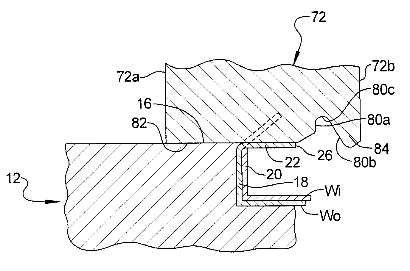
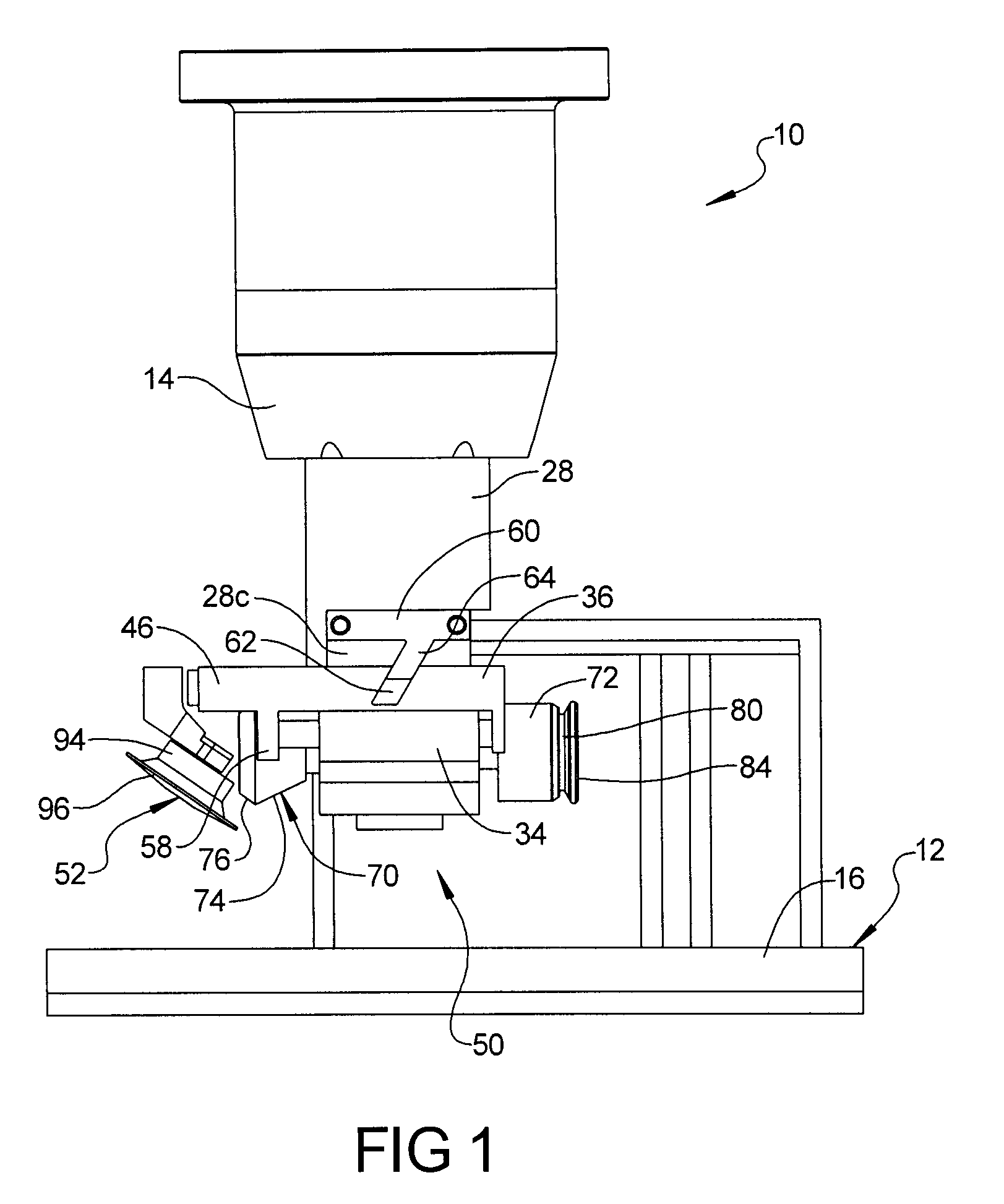
[0052]Referring now to the drawings, FIG. 1 is an environmental elevation view of a roller-type hemming apparatus 10 according to this invention positioned above a support frame 12 that is adapted to support a workpiece W. The hemming apparatus 10 includes a hemming head 14 that is operably connected to a work arm, such as provided on a multi-axis controllable robot hand, and is constrained for movement along a predetermined travel path around the frame 12 and relative to the workpiece W. The frame 12 is configured to nest or otherwise support the specific workpiece and includes a support anvil 16 that supports a roll ...


PUM

PropertyMeasurementUnit
angleaaaaaaaaaa
lengthaaaaaaaaaa
diameteraaaaaaaaaa

Abstract

The present invention pertains to a hemming head for performing a hemming operation which comprises a support housing adapted for securement to a robot arm on a first end, and having a first roller rotatably secured to a second end. The first roller has a cylindrical body, a head, and a groove between the body and head. The head has a diameter greater than the body, and the groove has a diameter less than the body. The groove also includes a canted surface that conjoins with the head. In use, the cylindrical body is adapted to engage and force a workpiece edge downwardly to a first position and the canted surface is adapted to engage and force the workpiece from the first position to a second position.

Description

CROSS REFERENCE TO RELATED APPLICATION[0001]This application claims the benefit of U.S. Provisional Application 61 / 209,931, which was filed on Mar. 12, 2009, the entire disclosure of which is hereby incorporated by reference.BACKGROUND OF THE INVENTION[0002]1. Field of the Invention[0003]This invention relates to hemming sheet metal and more particularly to a hemming apparatus and method for forming a generally flat hem between two metal panels. Even more particularly, this invention relates to a roller-type hemming apparatus for edge hemming vehicle closure panels, such as hemming door, hood, trunk, and deck lid panels.[0004]2. Description of the Prior Art[0005]In the automotive industry, hemming machines are conventionally used to attach two metal panels together. These metal panels include, for example, the metal panels to form the automotive hood, door panels, quarter panels, and the like.[0006]Hemming machines are disclosed in the patent prior art, including U.S. Pat. Nos. 5,26...

Claims


Application Information

Patent Timeline
Patent Type & Authority Applications(United States)
IPC IPC(8): B21D39/02
CPCB21D39/023B21D39/021
Inventor HARROW, AARON E.COX, THOMAS A.
Owner HARROW AARON E
Why Eureka
Try Eureka