Quasi self-contained energy storage and power supply system

Inactive Publication Date: 2010-11-11
SERISE TECH
9 Cites 65 Cited by

AI-Extracted Technical Summary

Problems solved by technology

From a point of view of tractive efforts distribution, this configuration is not optimal since they are concentrated in the locomotive, with underlying adhesion and power density problems.
Moreover, in traditional trains, the car braking is only pneumatic which induces a low capacity of braking energy recovery and the need to replace the brake pads frequently.
In ...

Method used

[0121]In order to optimize safety, the system according to the invention preferably inhibits any tractive effort at low speeds with a predefined threshold in order to prohibit autonomous startings; according to certain safety criteria, this inhibition could be removed.
[0123]The main constituent elements of the invention are already present in the individual electrical cars:[0124]energy storage system using electrochemical battery (nickel-cadmium, nickel metal hybrid, acid-lead, lithium ion, polymeric Li-ion, lithium polymeric metal, etc), it is estimated that a weight ranging between 150 and 400 kg and a volume between 0.15 and 0.5 m3 are sufficient for the storage of energy;[0125]electrical converter: using power semiconductors such as IGBTs or GTOs, in inverter, rectifier or chopper mode, these converters have been existing for over twenty years and are distributed by several manufacturers. It is estimated that a weight of approximately 50 kg and a volume of 0.05 m3 would be necessary;[0126]motor/generator: compact system of AC electrical motorization (induction motor) or DC motorization (preferably with permanent magnet), of the type of those replacing or complementing typical automobile heat engines in electrical or hybrid cars. It is estimated that a 0.5 m long and 0.35 m diameter motor weighing approximately 60 kg would provide the desired power; and[0127]an electronic controller with microprocessor programmed for the specific mode of operation of the invention requiring an original processing of information received from the sensors. The electronic controller is installed in order to minimize the acceleration and slope parasitic signals generated by vibrations and shocks due to rolling of the vehicle.
[0153]FIG. 9 shows on the curve (901) the evolution of the power consumed by the locomotive of a train equipped with the invention, in kilowatt-hours, and on the curve (902) the evolution of the total available energy stored in the cars equipped with the invention in kilowatt-hours. The assumption is made that the energy storage modules of the invention installed on each coach are ini...

Benefits of technology

[0163]Application of the invention: any train or convoy for which the sum of the moderate unitary powers of the invention installed on each bogie or axle will provide a substantial complement of power to the power of the locomotive or motor coach, proportional to the number of cars equipped with the system.
[0170]the significant reduction of the wear of the braking shoes.
[0171]Moreover, the invention can be installed independently on each bogie without any change in the drive mode of the locomotive or the motor coach.
[0172]According to the number of bogies thus equipped, the operator of the locomotive simply perceives minimal to substantial increases of the acceler...

Abstract

Quasi-autonomous system of energy storage and electrical motorization that can be installed on carrying axles or bogies of railway cars or road trailers to provide a tractive effort or electrical braking without an external power supply and assemblies, convoys and trains. The recharging energy of the energy storage system is principally obtained from regenerative braking and generated by the inertia of the convoy or by the traction of the convoy motor coach; the stored energy is returned as tractive effort when necessary. The system has a controller independent of all external control.

Application Domain

Technology Topic

Automotive engineeringTractive effort +5

Image

  • Quasi self-contained energy storage and power supply system
  • Quasi self-contained energy storage and power supply system
  • Quasi self-contained energy storage and power supply system

Examples

  • Experimental program(2)

Example

Example 1
Traditional Train Modified According to the Invention The train consists of a locomotive and 30 freight cars as represented in FIG. 5.
[0179]The locomotive is dimensioned for a maximum power of 3000 hp. The 30 cars are equipped with a system according to the invention on each of their two bogies, for a total of 60 systems also being able to produce a maximum power of 3000 hp (60×50 hp); 50 hp being the unitary power of the system according to the used invention.
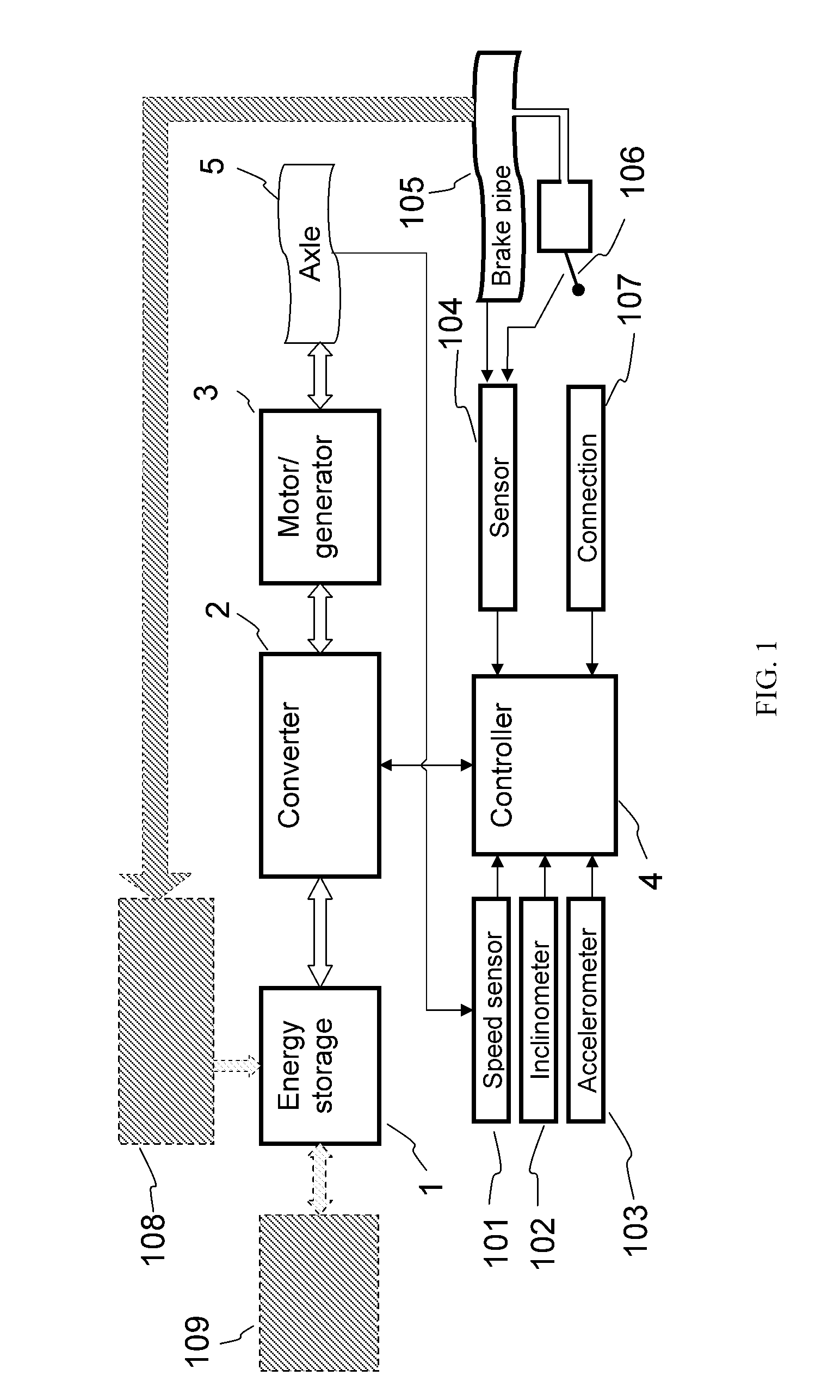
[0180]The system according to the invention used to equip the bogies consists of an energy storage module of polymeric lithium metal battery type marketed by the Batscap company under the trade name “Batscap battery”, of a converter of the semiconductive type such as an IGBT marketed by the Enova company under the trade name “Inverter 60”, of an AC type motor/generator marketed by the Enova company under the trade name “EDU-60”, of an electronic controller with microprocessor similar to those used in the industry of electrical vehicles and adapted to the specificities of the invention.
[0181]Let us take the case where in a traditional approach, as a function of the acceleration and of the slope, the locomotive should produce a power of 2000 hp. With the use of the invention, each bogie equipped with the invention can easily provide 15 hp during a long duration of time, which is 30 hp per car, which produces an addition of power of 900 hp (30×30), that is to say 45% of the initial power of the locomotive. For a same total tractive effort on the whole of the train, the power supplied by the locomotive is reduced by this same amount and the locomotive should not provide any more than 1100 hp (55% of the initial power).
[0182]The energy used by the systems installed on the bogies is then recovered during the braking and descent phases.

Example

Example 2
Use of the System of the Invention in a Marshalling Yard
[0183]A second example relates to the use of the system in switch yards, where the cars are divided and assembled into convoys by small power locomotives. Let us imagine that the train to displace contains 10 cars equipped with the invention on each one of their bogies: there are 20 bogies (10×2) each being able to provide 50 hp, therefore a maximum total power of 1000 hp (20×50). This power is very largely sufficient to displace the train at low speeds without any need to use the power of the locomotive, which is a reduction of the consumption of 100% in this case. One can thus carry out in certain cases the switching of cars without any locomotive.
[0184]Several other combinations can be explored, one of the main advantages of the invention being the possibility of installing it on a more or less high proportion of cars or trailers without any other consequence than the proportional increase or reduction in the available additional power.
[0185]Although the present invention was described using specific embodiments, it is understood that several variations and changes can be made to these embodiments, and the present invention aims to cover such changes, uses or adaptations of the present invention following, in general, the principles of the invention and including any variation of the present description which will become known or conventional in the field of use of the present invention, and which can apply to the essential elements mentioned hereinabove, in accordance with the scope of the following claims.

PUM

no PUM

Description & Claims & Application Information

We can also present the details of the Description, Claims and Application information to help users get a comprehensive understanding of the technical details of the patent, such as background art, summary of invention, brief description of drawings, description of embodiments, and other original content. On the other hand, users can also determine the specific scope of protection of the technology through the list of claims; as well as understand the changes in the life cycle of the technology with the presentation of the patent timeline. Login to view more.

Similar technology patents

Low friction chain

ActiveUS20080020882A1Reduce wearCombustion efficiency be improveDriving chainsEdge surfaceLow friction
Owner:TSUBAKIMOTO CHAIN CO

Insulator cleaning robot

Owner:STATE GRID INTELLIGENCE TECH CO LTD

Classification and recommendation of technical efficacy words

  • Low manufacturing cost
  • Reduce wear

Exercise equipment

InactiveUS6942605B1Low manufacturing costLow price of saleStraight-bar knitting machinesFootwearExercise equipmentPhysical medicine and rehabilitation
Owner:SUKHOVITSKY FELIKS

Hybrid aerial and terrestrial vehicle

ActiveUS20140131507A1Simple designLow manufacturing costConvertible aircraftsMicro-sized aircraftFlight vehicleTerrestrial locomotion
Owner:ILLINOIS INSTITUTE OF TECHNOLOGY

A ceramic insulator device for high voltage capacitor

InactiveCN101546636ALow manufacturing costReasonable structureSuspension/strain insulatorsHigh voltage capacitorsEngineering
Owner:王海龙

Denture

InactiveUS6139322ASuperior physical and aesthetic characteristicReduce wearImpression capsArtificial teethInterpenetrating polymer networkDentures
Owner:DENTSPLY RES DEVMENT
Why Eureka
Try Eureka