Heat exchanger apparatus

a technology of heat exchangers and baffles, which is applied in the direction of indirect heat exchangers, machines/engines, lighting and heating apparatus, etc., can solve the problems of increasing the likelihood of flow induced tube vibration, affecting the efficiency of heat exchangers, so as to reduce the pitch dimension of tubes, reduce the size of baffles, and reduce the effect of pressure loss

Inactive Publication Date: 2010-11-11
HOLTEC INT
View PDF15 Cites 27 Cited by
  • Summary
  • Abstract
  • Description
  • Claims
  • Application Information

AI Technical Summary

Benefits of technology

[0006]Alternatively, when the primary fluid is on the shell-side and the vapor to be superheated is on the tube-side, in order to maintain a very small pressure loss in the vapor flow and the primary fluid stream, conventional superheaters have been designed as bulky, large diameter pieces of equipment. Superheaters have also been designed with an increased baffle spacing and a decreased tube pitch dimension. However, these designs increase the likelihood of flow induced tube vibration. Therefore, it is an object of the invention to create a heat exchanger apparatus for use as a superheater with a primary fluid on the shell-side and the vapor to be superheated on the tube-side that has the smallest possible pressure loss in the vapor flow and heating fluid streams while reducing the effects of shell-side fluid induced vibration on the tube bundle.

Problems solved by technology

When the primary fluid is on the tube-side and the vapor to be superheated is on the shell-side, the vapor entering the superheater may carry water droplets which, if traveling at a high velocity, may damage the tubes upon impact.
Further, because the vapor entering the superheater is at a high pressure, possibly over 2,000 psi, making the diameter of the vessel large enough to reduce the vapor velocity will make the equipment exceptionally expensive.
However, these designs increase the likelihood of flow induced tube vibration.
The higher primary fluid flow rate results in higher shell-side cross flow velocities and an undesirable higher pressure drop.

Method used


Image

  • Heat exchanger apparatus
  • Heat exchanger apparatus
  • Heat exchanger apparatus

Examples


Embodiment Construction

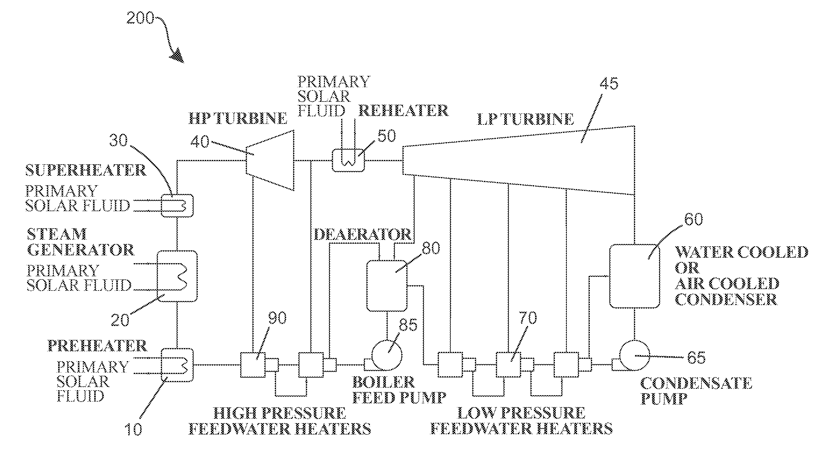
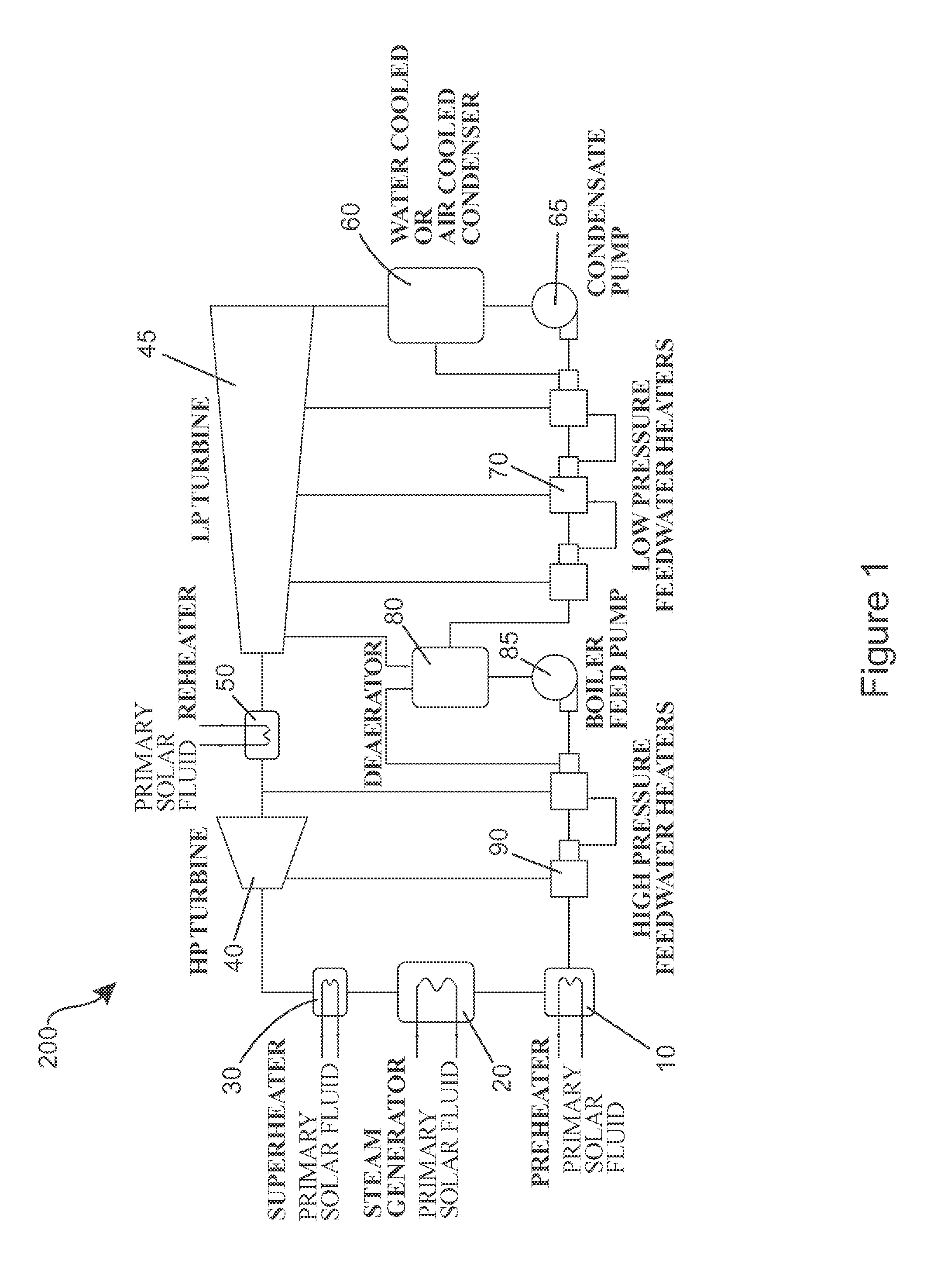
[0028]Referring to FIG. 1, a schematic of a solar power plant 200 is illustrated according to an embodiment of the present invention. While the invention is discussed in terms of (or incorporated into) a solar power plant 200, the invention is not so limited and can be used in any environment in which a superheater, preheater or other heat exchanger apparatus is required.

[0029]The solar power plant 200 generally comprises a preheater 10, a steam generator 20, a superheater 30, a high pressure (HP) turbine 40, a reheater 50, a low pressure (LP) turbine 45, an air cooled condenser 60, a condensate pump 65, a low pressure feedwater heater 70, a deaerator 80, a boiler feed pump 85 and a high pressure feedwater heater 90. All of the aforementioned components of the solar power plant 200 are arranged and operably coupled to one another as is known in the art.

[0030]In the solar power plant 200, the preheater 10 is used to preheat a secondary fluid, which is water in the exemplified embodim...


PUM


Abstract

A method, system and/or apparatus for reducing the pressure drop in a heat exchanger. In one aspect, the invention can be a heat exchanger comprising: a shell forming a cavity, the shell comprising an inlet for introducing a shell-side fluid into the cavity and an outlet for allowing the shell-side fluid to exit the cavity; a tube bundle for carrying a tube-side fluid, the tube bundle located in the cavity along a longitudinal axis; at least one stabilizing plate positioned within the cavity and arranged in a substantially transverse orientation, the stabilizing plate comprising a lattice structure having openings, wherein tubes of the tube bundle extend through the openings; and wherein the openings of the lattice structure are sized and shaped so that the tubes contact the lattice structure and a portion of the openings remain unobstructed by the tubes, thereby allowing axial flow of the shell-side fluid through the stabilizing plate.

Description

CROSS-REFERENCE TO RELATED APPLICATIONS[0001]The present application claims the benefit of U.S. Provisional Patent Application Ser. No. 61 / 175,963, filed on May 6, 2009, and U.S. Provisional Patent Application Ser. No. 61 / 175,967, filed on May 6, 2009, the entireties of which are hereby incorporated by reference.FIELD OF THE INVENTION[0002]The present invention relates generally to a heat exchanger apparatus and / or component therefor, and specifically to a heat exchanger apparatus and / or component therefor that results in a reduced pressure drop of the shell-side fluid while providing tube bundle stabilization.BACKGROUND OF THE INVENTION[0003]Generally, a tubular heat exchanger consists of a shell or large vessel with a bundle of tubes inside of the shell. Two fluids of different starting temperatures flow through the heat exchanger. The fluid with the higher starting temperature is known as the primary fluid and the fluid with the lower starting temperature is known as the secondar...

Claims


Application Information

Patent Timeline
Patent Type & Authority Applications(United States)
IPC IPC(8): F28F9/013
CPCF01K7/06F01K7/40F28D7/06F28F9/22F28F9/0219F28F9/0241F28F9/0136
Inventor SINGH, KRISHNA P.NADIG, RANGA
Owner HOLTEC INT
Why Eureka
Try Eureka