Test apparatus, test method, and device

a test apparatus and test method technology, applied in the direction of air-break switch details, instruments, air-break switch, etc., can solve the problems of errors, jitter and the like, and difficulty in accurately setting the delay tim

Inactive Publication Date: 2010-11-11
ADVANTEST CORP
View PDF10 Cites 15 Cited by
  • Summary
  • Abstract
  • Description
  • Claims
  • Application Information

AI Technical Summary

Benefits of technology

[0006]Therefore, it is an object of an aspect of the innovations herein to provide a test apparatus, a test method, and a device, which are capable of overcoming the above drawbacks accompanying the related art. The above and other objects can be achieved by combinations described in the independent claims. The dependent claims define further advantageous and exemplary combinations of the innovations herein.

Problems solved by technology

When the variable delay circuit is provided within the device, however, it is difficult to accurately set the delay time due to the effect of the processes, voltage, temperature, and the like of the device.
As a result, errors occur in the measurement results for jitter and the like.
Furthermore, when sampling the signal under measurement with a signal whose frequency is a non-integer multiple of the frequency of the signal under measurement, it is necessary to perform a data computation process after the sampling, and this causes an increase in the circuit size.

Method used


Image

  • Test apparatus, test method, and device
  • Test apparatus, test method, and device
  • Test apparatus, test method, and device

Examples


Embodiment Construction

[0026]Hereinafter, some embodiments of the present invention will be described. The embodiments do not limit the invention according to the claims, and all the combinations of the features described in the embodiments are not necessarily essential to means provided by aspects of the invention.

[0027]Hereinafter, some embodiments of the present invention will be described. The embodiments do not limit the invention according to the claims, and all the combinations of the features described in the embodiments are not necessarily essential to means provided by aspects of the invention.

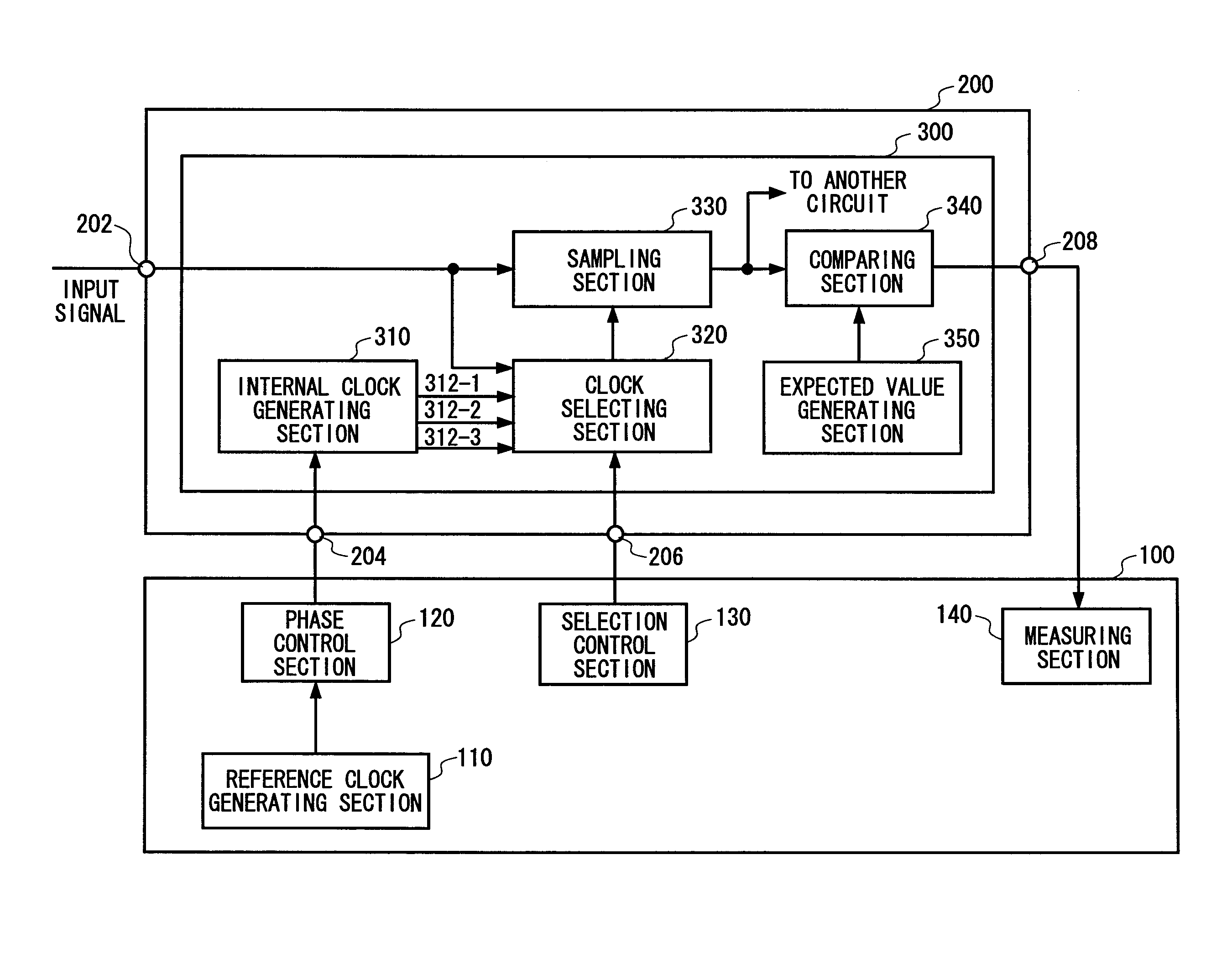
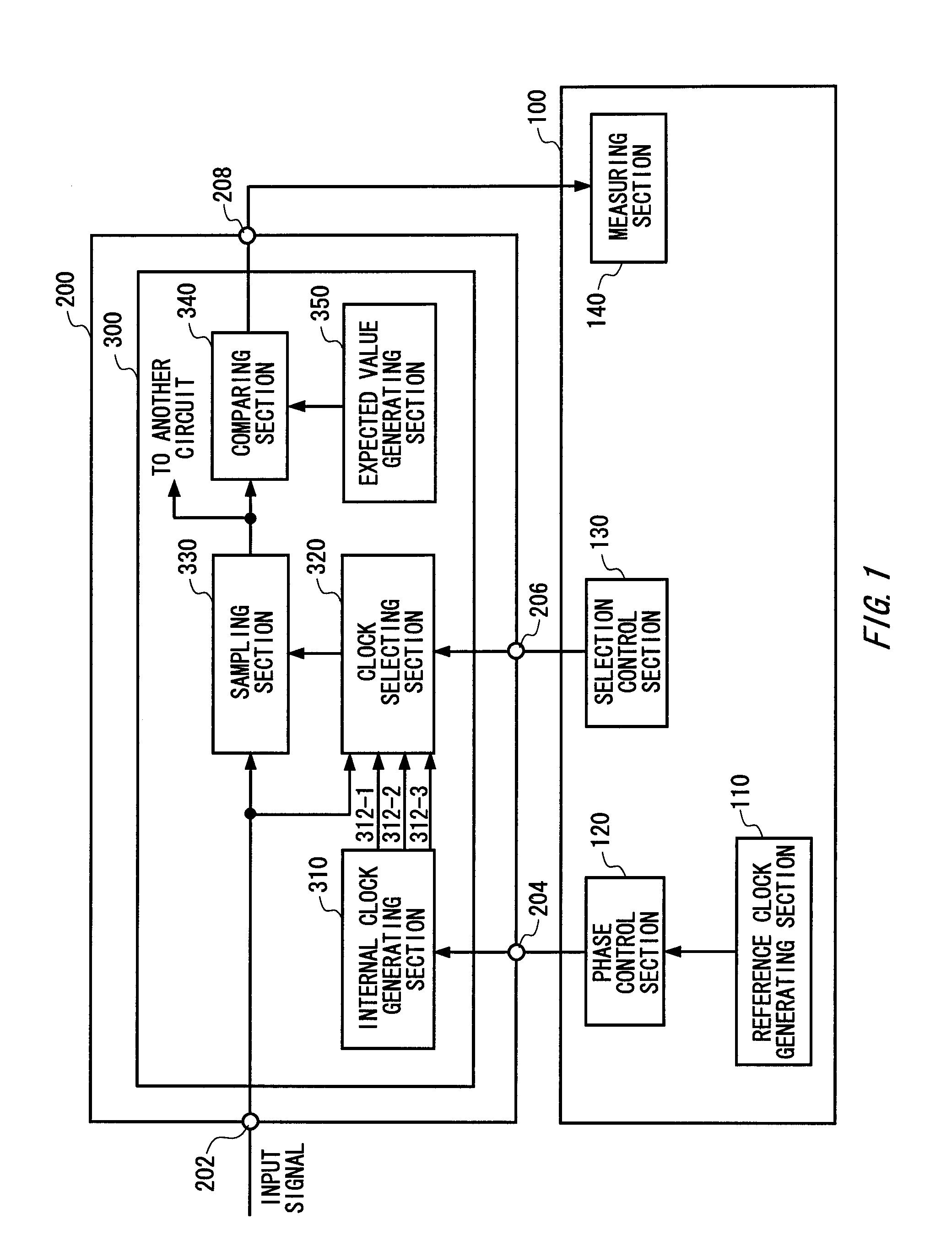
[0028]FIG. 1 shows exemplary configurations of a test apparatus 100 and a device under test 200 according to a first embodiment of the present invention. The test apparatus 100 tests the device under test 200. The test apparatus 100 may input to the device under test 200 an input signal having a prescribed pattern. The test apparatus 100 may judge acceptability of the device under test 200 based on a signa...


PUM


Abstract

Provided is a test apparatus that tests a device under test, wherein the device under test includes an internal circuit that generates a plurality of internal clocks having different phases based on a reference clock provided thereto, selects from among the internal clocks an internal clock having a predetermined relative phase with respect to an input signal having a frequency substantially equal to that of the internal clocks, and samples the input signal according to the selected internal clock. The test apparatus comprises a selection control section that fixes the internal clock selected by the internal circuit; a phase control section that, with the selection of the internal clock being fixed by the selection control section, sequentially shifts the phase of the internal clock by inputting the reference clock to the device under test while sequentially shifting the phase of the reference clock outside of the device under test; and a measuring section that measures a characteristic of at least one of the input signal and the internal circuit, based on the sampling result of the internal circuit.

Description

BACKGROUND[0001]1. Technical Field[0002]The present invention relates to a test apparatus, a test method, and a device.[0003]2. Related Art[0004]A known method for measuring characteristics such as jitter amount and an eye opening in a signal generated by a device involves providing a variable delay circuit that sequentially delays the signal under measurement within the device, and measuring the bit error rate for each delay amount. Another known method involves measuring jitter by sampling the signal under measurement with a signal whose frequency is a non-integer multiple of the frequency of the signal under measurement. The invention disclosed in Japanese Application Publication No. 2007-127645 is recognized as related art.[0005]When the variable delay circuit is provided within the device, however, it is difficult to accurately set the delay time due to the effect of the processes, voltage, temperature, and the like of the device. As a result, errors occur in the measurement re...

Claims


Application Information

Patent Timeline
Patent Type & Authority Applications(United States)
IPC IPC(8): H01H31/02
CPCG01R31/31709
Inventor NAGATANI, KENICHIISHIDA, MASAHIRO
Owner ADVANTEST CORP
Why Eureka
Try Eureka