Communication system and method for sample rate converting data onto or from a network using a high speed frequency comparison technique

a high-speed frequency comparison and data conversion technology, applied in the field of communication systems, can solve the problems of too high cost of sample rate conversion, and achieve the effect of accurately reproducing and increasing the accuracy or resolution of frequency differences

Active Publication Date: 2006-09-12
STANDRD MICROSYSTEMS CORPORATION
View PDF13 Cites 78 Cited by
  • Summary
  • Abstract
  • Description
  • Claims
  • Application Information

AI Technical Summary

Benefits of technology

[0016]Multimedia devices that produce multi-channel, high bit resolution can avoid the complex sample rate conversion at the source port and instead can simply use a phase comparator at the source. The phase comparator can determine the phase difference within one sample clock and pass that phase difference to the destination, which recreates the source port sample rate with minimum jitter. Thus, while the source local clock can be a crystal oscillator, the destination clock is recreated from the source clock by transmitting the phase difference (or frequency difference calculated from relative changes in phase difference) across the network.
[0021]In the case of a sample rate converter embodiment, a comparator within the source port compares a change in a phase difference between the frame transfer clock and the sampling clock local to or distal from that node. Preferably, sample rate conversion occurs in the destination port, whereby the phase or frequency difference information is sent from the comparator in the source port. The change in phase difference can be calculated on successive cycles of the frame transfer clock, or possibly N cycles apart. Calculation on successive cycles will allow frequency difference detection to occur faster than if calculation must wait until the Nth cycle. However, calculation N cycles apart will increase the frequency difference accuracy or resolution. A bit value for each phase difference, or a bit value representing a change in phase differences, or a bit value representing frequency difference calculated from the change in phase differences can be sent across the network to the sample rate converter in the destination port.
[0022]In the case of an arbitrary rate synchronous embodiment, the source and destination ports create the appropriate local clocks by multiplying and dividing the FSR of the network. The source port may require a master clock of, for example, 27 MHz. To create the master clock from a 48 KHz FSR, the multiplier and divider has a ratio of approximately 1125 / 2. To create the master clock from a FSR of 44.1 KHz requires a multiplier and divider ratio of 30000 / 49. The destination port also includes a multiplier and a divider to produce a master clock. The master clock in the destination port, however, need not be 27 MHz. Instead, the master clock in the destination port can be used directly to synchronize the frames of data to the rate in which the data streams from the source so that the data can be accurately reproduced in the local amplifier and / or digital-to-analog converter within the destination port. Depending on the destination port local frequency required to recompile the streaming data and the FSR of the network, the master clock within the destination port either has a frequency of some integer multiple of approximately 1.0, 147 / 160 or 160 / 147 of the FSR.

Problems solved by technology

If sample rate conversion proves too costly for certain multimedia devices, and the source sampling clock (fs) cannot be synchronized to the network frame transfer rate, then a PLL can be used and confined solely to the destination.

Method used


Image

  • Communication system and method for sample rate converting data onto or from a network using a high speed frequency comparison technique
  • Communication system and method for sample rate converting data onto or from a network using a high speed frequency comparison technique
  • Communication system and method for sample rate converting data onto or from a network using a high speed frequency comparison technique

Examples


Embodiment Construction

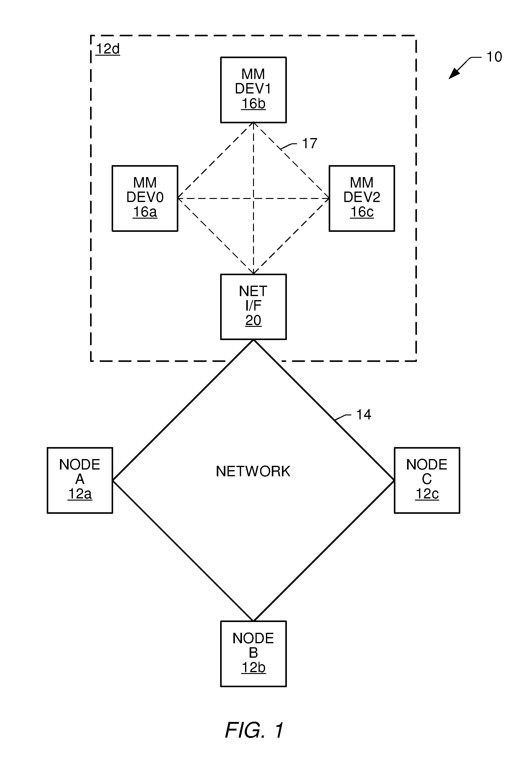
[0036]Turning now to the drawings, FIG. 1 illustrates one example of a communication system 10. Communication system 10 includes an interconnected plurality of nodes 12. For sake of brevity, only four nodes are shown. However, it is understood that system 10 can include more than four nodes and can also include multiple interconnected networks. The network shown in FIG. 1 is a ring or loop. However, it is also understood that the network backbone can be bus, star, or any other topology available to a network. Coupled between nodes 12 are corresponding transmission links 14. Transmission links 14 can be optical, acoustic, or electrical (wired or wireless).

[0037]Each node 12 is preferably localized to a particular area. Within each node is at least one multimedia device. As shown in node 12d, a node can have more than one multimedia device 16. If more than one localized device 16 is present, then a local transmission line or local bus can be used between multimedia devices 16 in eithe...


PUM


Abstract

A communication system, source and destination ports of the communication system, and methodology is provided for transporting data in one of possibly three different ways. Data is transported across the network at a frame sample rate that can be the same as or different from the sample rate or master clock within the source port or the destination port. If the sample rate of the source port is known, the sample rate of the destination port can be created using a PLL within the destination port and simply employing a phase comparator in the source port. The phase comparator forwards the phase or frequency difference of the network transfer rate and the source sample rate to the destination port, which then generates a local clock equivalent to the source which then compiles audio data being played at the same rate in which it was sampled at the source. Where economically feasible, sample rate conversion can be used at the source. However, sample rate conversion at the destination is preferred if the source sample rate is forwarded across the network relative to the frame transfer rate of the synchronous network. The sample rate converter simply produces a play rate from the transmitted information at the destination. Again, however, sample rate conversion compares relative phase difference changes similar to the phase difference compared in the digital PLL mode. As a further alternative, sample rates within the source and destination ports can be derived from the network frame rate using fractional dividers in the source and destination ports.

Description

BACKGROUND OF THE INVENTION[0001]1. Field of the Invention[0002]This invention relates to a communication system, such as a network of interconnected nodes for sending streaming data and non-streaming data across a network having a frame transfer rate that is dissimilar from the local clock rate of the data at the source or destination nodes. The source and destination nodes can include a port, wherein the source port preferably includes a phase comparator that compares successive changes in phase between the network frame rate and the source or sample rate and forwards the pertinent information to the destination port which can then perform sample rate conversion using the sample rate of the source relative to the frame transfer rate.[0003]2. Description of the Related Art[0004]Communication systems are generally well known as containing at least two nodes interconnected by a transmission line. Each node may include a data source and / or a data destination. If the node is configured...

Claims


Application Information

Patent Timeline
Patent Type & Authority Patents(United States)
IPC IPC(8): H03M7/00H04J3/06
CPCH04J3/0647H04L7/0029
Inventor KNAPP, DAVID J.MADDOX, JOHN G.GAALAAS, JOSEPH B.
Owner STANDRD MICROSYSTEMS CORPORATION
Why Eureka
Try Eureka