Pulsed radar level gauging with relative phase detection

a technology of relative phase delay and radar level gauge, which is applied in the direction of level indicators by physical variable measurement, liquid/fluent solid measurement, engine lubrication, etc., can solve the problem of small waveform shift very difficult to detect, amplitude detection as the only method for identifying the location of echo in the tank signal suffers from limitations, and the resolution of a/d converter needs to be relatively high, so as to achieve accurate detection of surface echoes

Inactive Publication Date: 2008-05-08
ROSEMOUNT TANK RADAR
View PDF22 Cites 65 Cited by
  • Summary
  • Abstract
  • Description
  • Claims
  • Application Information

AI Technical Summary

Benefits of technology

[0005]It is an object of the present invention to relax the system requirements, and to provide an improved method for accurate detection of surface echoes in a tank signal.
[0020]The invention is based on the realization that major improvement of measurement performance, compared to amplitude detection only, can be achieved by discrimination of the phase difference between the reflected signal and a reference. The detection is further independent of the pulse waveform and modulation, significantly reducing the requirements on pulse modulation.
[0030]The relative phase shift can be determined by calculating two phase-frequency pairs each comprising the phase of the Fourier transform for a specific frequency, and determining a slope between these phase-frequency pairs. This provides an efficient way to determine the relative phase, saving processing power.

Problems solved by technology

However, amplitude detection as the only method for identifying the location of an echo in the tank signal suffers from limitations.
The reason is that the peak is in fact the envelope of a waveform, making a small shift of the waveform very difficult to detect.
In addition to this, the resolution of A / D converter needs to be relatively high, as limitations in system causing saturated signals may further reduce measurement performance.

Method used


Image

  • Pulsed radar level gauging with relative phase detection
  • Pulsed radar level gauging with relative phase detection
  • Pulsed radar level gauging with relative phase detection

Examples


Embodiment Construction

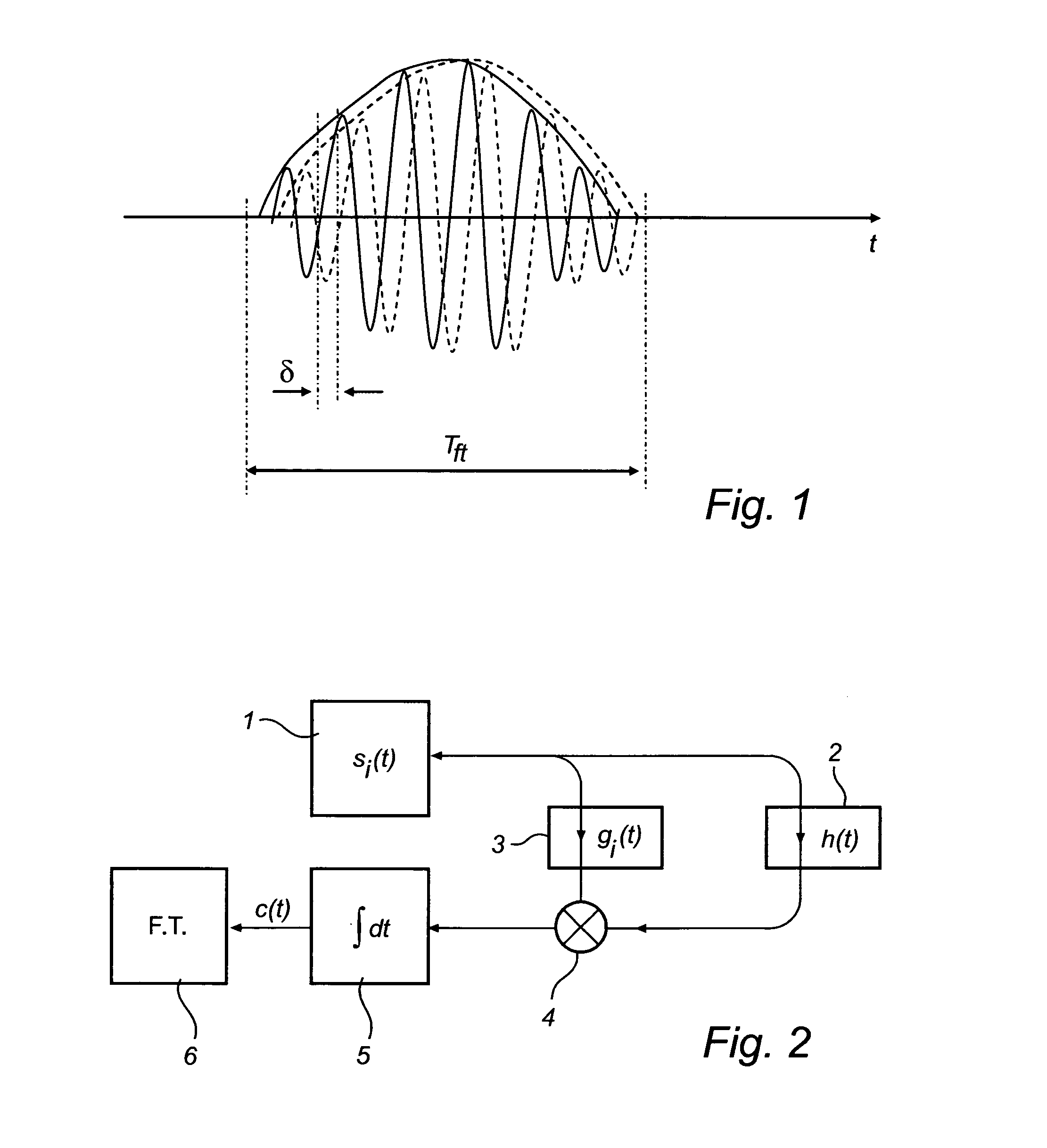
[0040]FIG. 2 shows a schematic model of a radar level gauging system according to an embodiment of the present invention.

[0041]A transmitter 1 produces a train of identical pulses si(t) that is transmitted via an unknown channel 2 with impulse response h(t). A copy of the transmitted pulse train is transmitted via a reference channel 3 having an impulse response g(t) representing a known and varying relative time delay t0+τi i.e. gi(t)=δ(t−(t0+τi)).

[0042]The two inputs are cross correlated (i.e. mixed 4 and integrated 5) to form a cross correlated signal c(t) and finally Fourier transformed 6 as a function of the minimum delay t0. The result out of the Fourier Transform can be written as:

C(ω)=|S(ω)|2H(ω)  Eq 1

[0043]Equation 1 represents the power spectral density |S(ω)|2 of the transmitted signal multiplied with the Fourier Transform H(ω) of the unknown channel. For the special case when the unknown channel is a delayed response, h(t)=δ(t−tch), the expression becomes

C(ω)=|S(ω)|2 exp...


PUM


Abstract

A method for determining a process variable of a product in a tank based on a time delay of electromagnetic waves. The method further comprises forming a measurement signal comprising a sequence of values, each value representing a time correlation between a pulse of a reference signal and a reflected signal, sampling and digitizing this measurement signal to form a digital signal, identifying a time window of the digital signal including the surface echo peak, determining a relative time period between a reference time corresponding to the predefined reference and a beginning of the time window, time-to-frequency transforming the digital signal in the time window to obtain a phase spectrum, determining a relative phase shift of the spectrum and using the relative phase shift to calculate a corresponding time shift, and determining the time delay by adding the relative time period and the time shift.The invention is based on the realization that major improvement of measurement performance, compared to amplitude detection only, can be achieved by discrimination of the phase difference between the reflected signal and a reference. The detection is further independent of the pulse waveform and modulation, significantly reducing the requirements on pulse modulation.

Description

TECHNICAL FIELD[0001]The present invention relates generally to a method and a radar level gauge for determining a propagation delay for a signal emitted into a tank and reflected by a surface of a content in the tank. More specifically, the invention relates to radar level gauging based on detecting relative phase delay.BACKGROUND OF THE INVENTION[0002]Radar level gauges are used for making non-contact measurements of the level of products such as process fluids, granular compounds and other materials. These devices utilize an antenna or a probe to transmit electromagnetic waves toward the material being monitored and to receive electromagnetic echoes which are reflected at the surface of the material being monitored. The relationship between transmitted and received waves is then used to determined the location of the reflection, i.e. the surface.[0003]In a pulsed radar level gauge, constant power electromagnetic pulses are transmitted into the tank with a repetition frequency typ...

Claims


Application Information

Patent Timeline
Patent Type & Authority Applications(United States)
IPC IPC(8): G01F23/28
CPCG01F23/284
Inventor NILSSON, VALTERWENGER, FABIAN
Owner ROSEMOUNT TANK RADAR
Why Eureka
Try Eureka